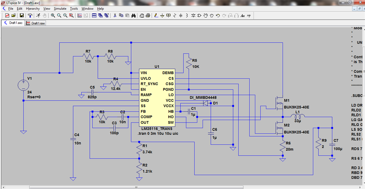
Hello,
I'm using the LM25116 SPICE model in a synchronous buck converter circuit simulation which I created according to the guidelines in the LM25116 data sheet. For the most part the model is behaving as expected, except that I cannot get it to come out of diode emulation mode. I've placed a 10K resistor between the DEMB pin and ground as the data sheet suggests, in order to force synchronous operation. But I see no switching of the low side mosfet, and the LO output from the model is pinned to 0V. I also don't see any voltage across the 10k resistor that I connected between DEMB and ground. According to the data sheet, I should see about 0.45V. Even when the output voltage hits steady state (5V) after startup, the part continues to run in diode emulation mode.
Any insight into why this is happening would be appreciated. Is this a known problem with the model, or could it be a mistake in my schematic? If it's a problem with the model, are the some instructions on how I can correct it?
I'm using LTSPICE IV simulator.
Thanks,
Adam


