


Hello,
I downloaded “OPA354 TINA-TI Reference Design from OPA354A-Q1” product page.
I changed input waveform from sin wave to square wave and did transient simulation.
(using attached file)
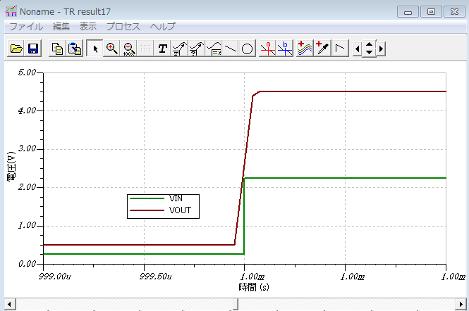
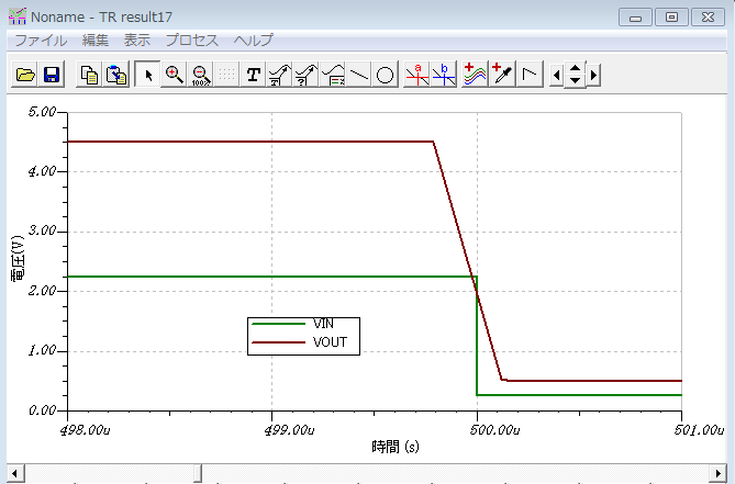
VOUT start to rise before VIN start to rise.
I think VOUT must start to rise after VIN start to rise.
Could you please explain the reason why VOUT start to rise before VIN start to rise.
Best Regards.
