This thread has been locked.

If you have a related question, please click the "Ask a related question" button in the top right corner. The newly created question will be automatically linked to this question.

TPS62410 simulation problem

Other Parts Discussed in Thread: TINA-TI, TPS62410

Dear:

I download the TPS62410 TINA-TI Transient Reference Design from TI web. And then open it with TINA-TI v9.

When I select "Analysis -> DC Analysis -> Calculate nodal voltages or Table of DC results "  It will be warning: "Operating point not found"

I want to know how to solve it?  Thanks.

Like bellow:

  • user3314695,

    The reference design is a transient reference design. Please run a transient simulation. Running a DC analysis on a transient model would not yield any meaningful results.

  • Dear Britt,

    I got it. Thanks.

    But I need to run DC analysis use TPS62410,  I also download the TPS62410 TINA-TI Transient Spice Model (TINA-TI Spice Model) from Web of TI, 

    it is can't to run DC analysuis too.

    How can I get the spice model of TPS62410 which can run DC analysis ?  Thanks.


  • user3314695,

    What do you mean that you need to run DC analysis on the TPS62410? What are you trying to find out from a DC analysis? Since the device is completely off at the DC bias point, what are you hoping to learn? A SMPS does not function in a simulator at DC.

    I think that you are misinterpreting what a DC analysis in SPICE means. DC analysis is not a steady state analysis where the device has started up and is running. That is a time based simulation (transient). The DC analysis will only provide you the t=0 information (the device is off and the voltages in the circuit are applied only, no function of the device would be present). At DC, the output voltage would be 0V, the input voltage would be 0V (unless you are using a fixed voltage source where the voltage would be Vin), the currents would all be very near 0 as no time has passed for allowing the currents to conduct, and the device responses would be very uninteresting.

  • Dear:

    Thanks for your reply.

    I want to find the voltage or current value of every points in the circuit.  The Vin is  fixed voltage source.


  • user3314695,

    In order to be able to display all of the nodes in the circuit, enter the Analysis-->Options menu. Make sure that the Save all analysis results box is checked:

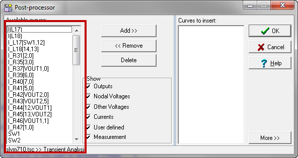
    Next, run the transient simulation. It is set up to run for 900uS. Once the simulation is complete, you may choose any of the nodes for display in the Diagram window by clicking on the Post processor button:

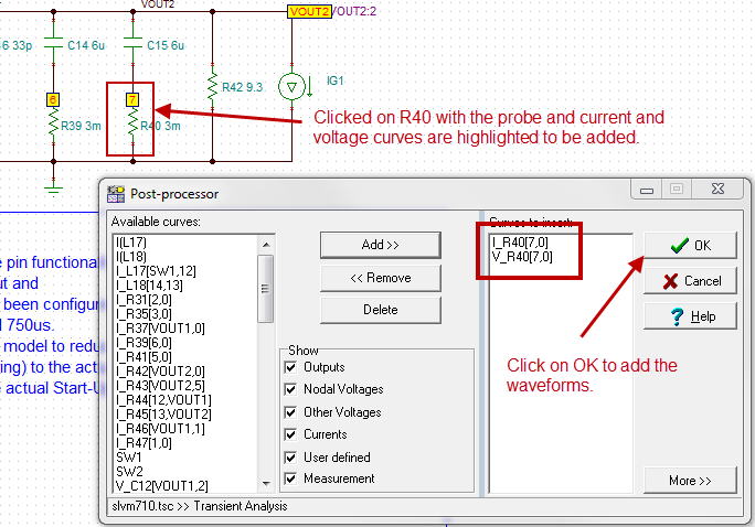
    A full list should be on the left hand side of the window. You can also use the probe and touch the node or component to set the curve to be displayed

    Simply click on the name in the left hand window, click the Add>> button and hit OK. That waveform will be added to the Diagram window. If you click with the probe, the waveform you clicked will be highlighted in the left hand window. Click the Add>> button and click on OK.

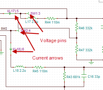
    You can also add current arrows or voltage meters to the circuit and the curves will be automatically displayed when the simulation is completed.

    This particular simulation takes a few minutes to run since it is performing a load transient test.

  • Dear Britt,

    It is a good idea, I got it. Thanks very much!