This thread has been locked.

If you have a related question, please click the "Ask a related question" button in the top right corner. The newly created question will be automatically linked to this question.

Tina, simulate resistance change over time in Wheatstone bridge

Other Parts Discussed in Thread: TINA-TI

Hi,

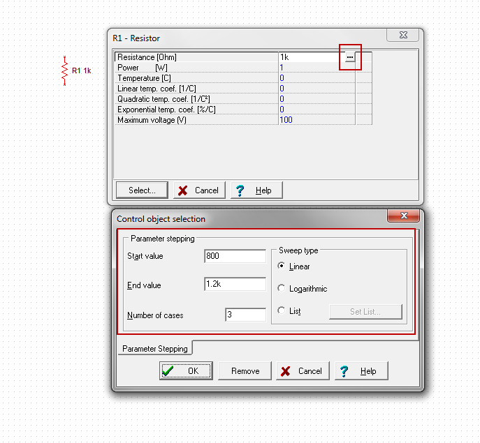
Is it possible to run the AC transfer characteristic in Tina but as a source use resistor which resistance changes like sinus function? I'm trying to simulate a bridge sensor.

Many thanks,

Krzysztof

  • Krzysztof,

    I do not think that is possible in TINA-TI.

    Do you have a model for a resistor that changes like a sin function?

    Not sure exactly what you are trying to simulate, but I would guess that if the resistance is changing like a sin wave, the voltage and/or current will also be changing in a similar manner.

  • Hi Britt,

    Thanks for your reply, I don't have a resistor model that changes resistance like sin wave. I'm beginner TINA-TI user and I'm trying to simulate quarter bridge Wheatstone circuit like this:

    Where R15 would change over time. Is such simulation possible, please?

    Thanks,

    Krzysztof

  • Krzysztof,

    Does it have to vary with a sin wave? You can run the simulation with multiple values using the Control object in TINA-TI, but this is multiple simulations with different values for R15. Use the Select Control Object:

    The cursor will change and you select the resistor with it. Click on the ellipsis and fill in the resistance values by list or sweep. Click on OK and an asterisk will appear next to the resistor value.

    Run the simulation and each sim will use a different value of the resistor. The simulations will all appear in the Diagram Window when completed. The legend can be used to show you the multiple curves.

    Alternatively, you could use a voltage controlled resistor using a controlled source and a sense source. The resistance is then controlled by a sin wave voltage source. I have set up the attached example .TSM file for a 1K resistor when the voltage applied is 1V. You can change it to whatever value you need. Nodes C4 and C5 are the controlling voltage and nodes R1 and R2 are the resistor nodes.

    vcr_1k.TSM

    And an example circuit using the Ohm meter:

    VCR_test.TSC

    I hope this helps.