This thread has been locked.

If you have a related question, please click the "Ask a related question" button in the top right corner. The newly created question will be automatically linked to this question.

LDC coil design - Export CAD

Hi all,

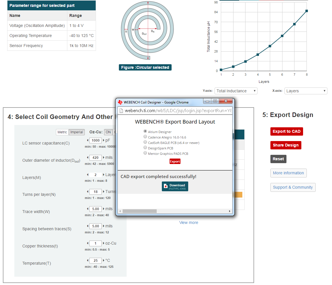
I would like to export coil design through webench.

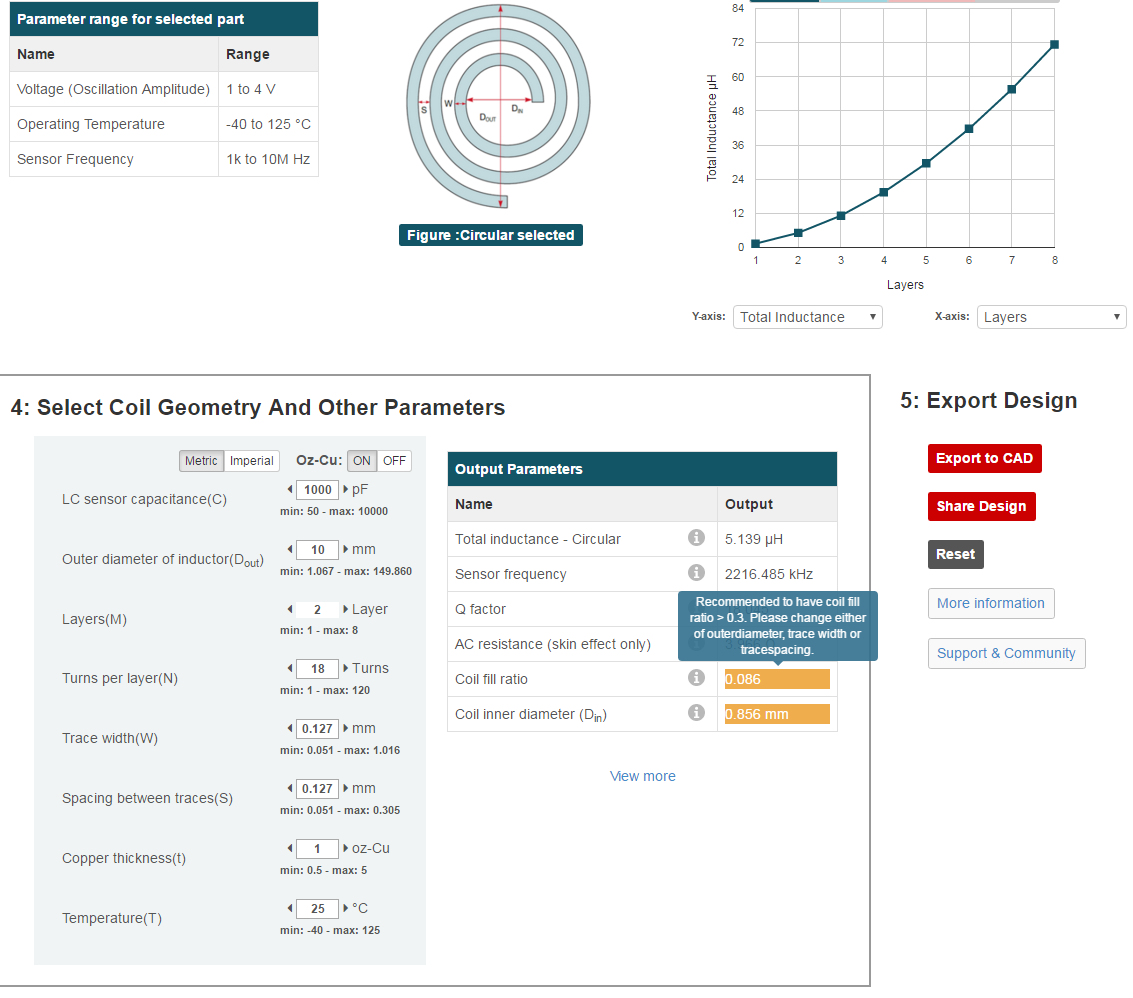
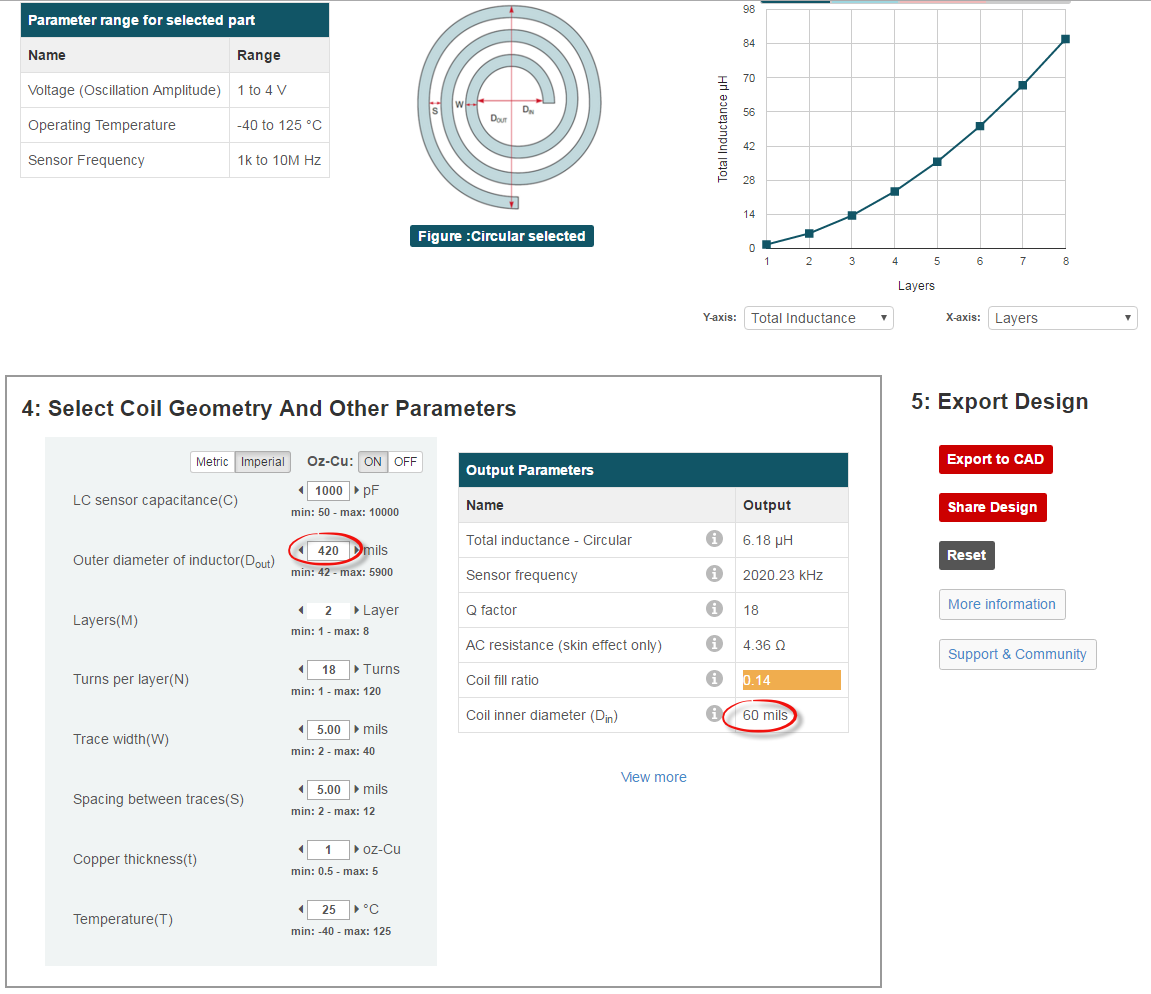
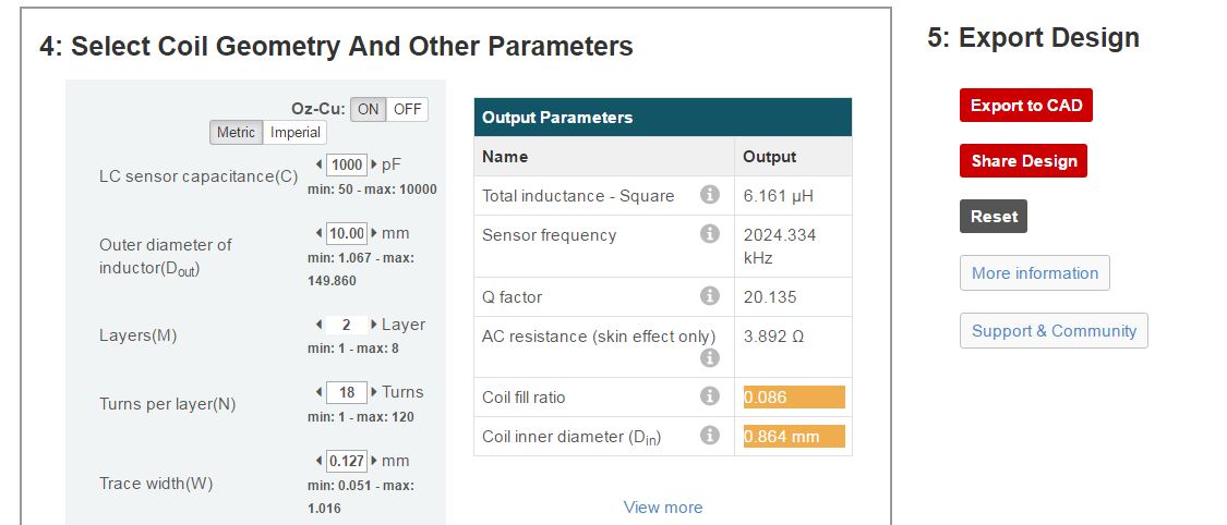
As below picture, if coil inner diameter show the warning, I cannot export to CAD about this design. However, LDC application engineer said that coil inner diameter doesn't impact on the performance. The most important thing is to increase the inductance.

To increase the inductance as larger as possible, the coil inner diameter should be smaller.

Would you let me know how to export to CAD despite of the warning?

Thanks in advance.

Best regards,

Sammy

  • Hi Sammy,

    Thanks for choosing WEBENCH Coil Designer for designing coil for your application.

    Following is the link to guidelines for designing the coil using WEBENCH Coil Designer. 

    www.ti.com/.../inductive-sensing.page

    Custom coil design made easy!

    1. Determine the maximum size inductor that can be used in the application, and set the Dout value to that size.
    2. Based on the PCB manufacturing rules, set:
      • Trace width and space to the minimum permitted, typically 4mils (0.1mm) or 6mils (0.15mm)
      • Copper thickness, typically 1oz-cu (~35 µm). Thicker is better.
    3. Set the number of layers to match the number of board layers in your design.
    4. Set the Capacitance – the range of 500pF to 2nF is typically near the optimum unless a specific sensor frequency is needed. Adjust the capacitance as needed if your sensor frequency is not within the device limits.
    5. Set the number of turns so that the ratio of Din/Dout is >0.3.
    6. Export custom design into your desired format.

    Regarding the coil design and export condition you encountered, if you hover over the highlighted fields you will see the message.

    As per the design guidelines the fill ratio (inner dia / outer dia) should be > 0.3 which is not in the case.

    Next, coil inner diameter is too small. As you can see from the message it needs at least 60mil or 1.524mm to place the via in the center and with the current inner diameter it is not possible. Since inner diameter is calculated from outer diameter you need to increase the outer diameter to fix this issue.

    Finally if you click on export button, you will see a message (top right in below snapshot) that the current outer diameter (and therefore calculated inner diameter based on turns, trace width and spacing) is not large enough to place the via at the center.

    In summary, it is not possible to create a coil with the selected parameters as there is there is no space in the center to place via. It is not an issue with the tool, we can not do it manually. The solution is to have a minimum inner diameter so that we can keep a via at the center which you can do by increasing the outer diameter assuming you want all other parameters (e.g. turns, trace width, trace spacing etc) to be same.

    I have increased the outer diameter to 420mil or 10.668mm (original was 10mm in your snapshot) which gives me inner diameter of 60mil. The coil fill ratio is 0.14 which is still < 0.3.

    With this change I am able to export the design as for two layer coil now we have enough space in the center to place a via.

    Here is the snapshot of successful export.

    The Coil:

    Here is the link to open this design and export.

    http://webench.ti.com/wb5/LDC/#/spirals?shape=Circular&amp;lcTanKCapacitance=1000&amp;turns=18&amp;layers=2&amp;spaceBetweenTrace=5&amp;traceWidth=5&amp;copperThickness=1.000&amp;dout=420&amp;temperature=25&amp;partno=LDC1614&amp;voltage=1.8&amp;x12=4.00

    Regards,
    Pradeep