This thread has been locked.

If you have a related question, please click the "Ask a related question" button in the top right corner. The newly created question will be automatically linked to this question.

"Idealized" FDA Model used in section 4.1 of SLVA417

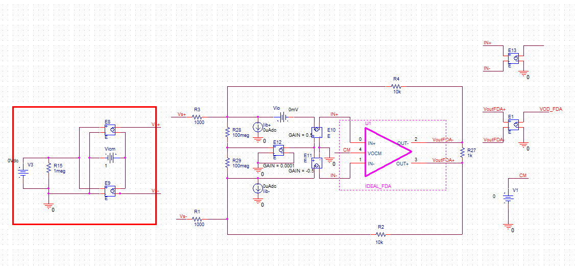
This is for John Miller (author of SLVA417).  Could you please provide the SPICE models you used for your "idealized" FDA model?  I would like to confirm the same simulation in the appnote before I use the model in a some alternate circuits than the example one used in the appnote.  I made a stab at it with the ideal circuit below, but numerically it is a little off compared to the example.  I also included the "ideal" fda I made.  I tried to make sure all the voltages and currents are oriented in the directions defined in the appnote.   One notable exception is the input voltage source direction was reversed from the picture, I am guessing the original pic or stipulated input voltage (1V) was a typo.  I am hoping the issue is just a source direction definition.

  • Tracey,

    Its been a while, but to the best of my recollection, the attached image shows the top-level schematic of the FDA model used in the app note.
    The voltage and current sources are used to provide VOS, IIB and IOS. Dependent voltage sources E10, E11 and E12 model CMRR.

    The netlist of the idealized FDA itself (U1) is in the attached netlist ideal_ fda_wths4509_params.lib.

    Hope this helps.

    Regards,
    John

    ideal_ fda_wths4509_params.lib

  • Thanks for the post John.  It looks like your ideal FDA, at least at DC, is very similar to mine.  Only major difference is that I cannot see how you control the CMRR in the model.  Oh well, no biggy.  I was finally able to reproduce your numerical results by reversing the polarity on my input bias current sources.  It looks like I must have had them backwards.  Here is the update simulation with the correct answer and some arrows added to indicate the intended bias current flow direction.  The current is flowing in the directions indicated in figure 3 in SLVA417, but my magnitudes are messed up compared to the figure.  So there is some confusion in the figure as to which direction that current is actually flowing, but oh well, I think I can reconcile the differences and take confidence in the model.  Thanks for your help.

  • The picture did not attach.  Trying again

  • Attaching picture for Tracey...

    John, do you have any updates?

  • Jason,

    The CMRR is controlled by dependent sources E10-E12 in the diagram.
    You can adjust CMRR with the E12 gain. Increasing E12 makes the CMRR worse; decreasing it makes the CMRR better.

    With respect to the bias currents, I think they should be flowing out of the node.
    The usual convention is for currents flowing into the node to be considered positive, and since the signs are shown as negative, the currents were flowing out of the node.

    Regards,
    John