This thread has been locked.

If you have a related question, please click the "Ask a related question" button in the top right corner. The newly created question will be automatically linked to this question.

LM3481 and TINA-TI

Other Parts Discussed in Thread: LM3481, TINA-TI

Hi,

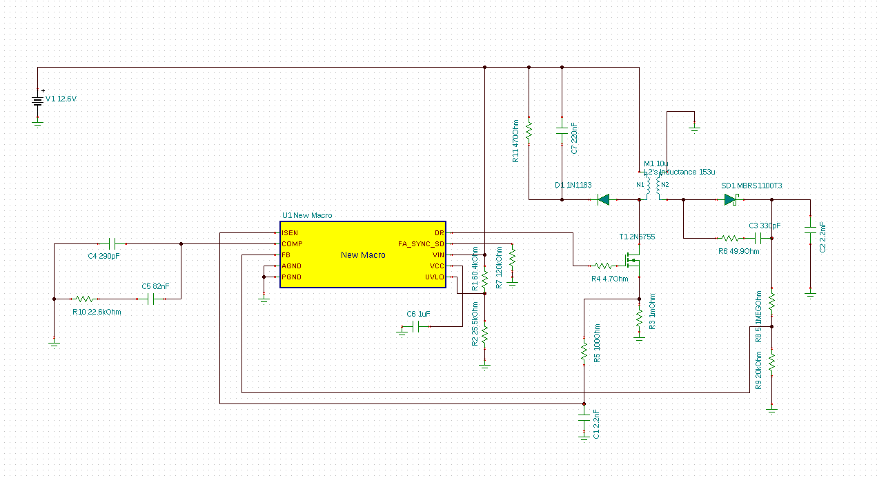
I'm new to both TINA-TI and the LM3481 and apparently need help to get started. I'm using the LM3481 transient model. When I try to run a DC analysis -> Table of DC results the analysis run a number of iterations and terminates with a warning: "Operating point not found"  and points to the LM3481 model D_D11. I get no other result from the analysis. Since I'm new to both the component and the simulator I'm a bit lost. Most likely it's my error, but I can't figure out what I've done wrong. To be honest, I haven't really designed the circuit yet and some of the components will probably not survive the stress in the circuit because I haven't selected the appropriate parts yet but I would think that TINA-TI should be able to simulate. If I do a "transient" analysis which I assume is the analysis which match the model the circuit appear dead. One final note: I am on a Linux workstation so I run TINA-TI in a wine simulator but it does seem to work perfectly so I don't think that's the cause of my problems.

I would have liked to attach the TINA-TI schematic file but it seems it gets inserted into my post rather than attached so I don't think that would work. Instead I have included a screen capture of the schematic. The application is a high voltage capacitor charger for a high end photo flash and currently I'm trying to evaluate the LM3481 for this purpose.


I hope you can help me to get started with the LM3481 and TINA-TI :-)

Best Regards

Niels

  • Hi Niels,

    You have correctly guessed that it is a Transient model and hence it will work with Transient simulation mode only. DC Analysis may not work on this. Regarding LM3481 boost controller, I would recommend you develop the design using WEBENCH, where you can insert your input and output conditions and run the simulations online, modify circuit components and perform different operations like Optimizations for cost vs efficiency, Thermal analysis and Operating Values check. It serves two purposes in your case, you don't have to worry about Linux vs Windows platform and it will give you a very good starting point, later to take the online schematic to TINA-TI or export schematic to CAD tool for PCB development.

    Ideally, the TINA-TI Transient Analysis should work and at least give you simulation window or error message, if something is wrong with schematic or analysis parameters. We can't help in circuit debug without TINA-TI schematic file. The file attach procedure will add schematic as download link only. So please follow it to upload the file (which you seem to be doing correctly, but in doubt deleting it back again).

    Hope this information helps. Kindly let us know if you need further assistance.

    Thanks!!

    Best Regards,
    Mahavir Jain.
  • Hi Neils,

    Since you are new to TINA-TI, I would highly recommend that you take this short video training. It will answer a lot of the basic questions that might come up and provide some handy tips.

  • Thank you very much Mahavir :-)

    Prior to setting out to simulate in TINA-TI I did try WEBENCH but it can not produce a usable result for my requirements. See attached screen shot.

    I would think that you can see the input parameters I entered but just in case no: Vin 10.8V - 14V, Vout 300V, Iout 0.1A. I think the LM3481 should be able to do this with the correct external components.


    I've been working a bit more on my schematic and finally have seen some life in the transient simulation. I replaced the battery with a unit step source with the nominal voltage of the battery. After fiddling around in TINA-TI for some time I did get output from the transient simulation but the polarity of the transformer output was wrong so I flipped the transformer output and now can get the converter to output 12.6V (equal to the input voltage)  which is quite a bit away from my design target of 300V. I will try to attach the TINA-TI schematic to this post. I know that there still is an issue of choosing the appropriate component values but even without doing that I'm surprised by the transformer polarity.


    Any suggestions would be highly appreciated.

    Best regards

    Niels

    flash_hv_gen.tsc

  • Thank you Nikhil,
    I did read through the "Quick Start Guide SBOU052A" for TINA-TI before starting to use TINA-TI and posting on this forum. Most of the stuff explained in this guide is almost self explanatory when you use the software. I do find TINA-TI quite easy to use. I did however pick up some very useful hints from the video you linked to so this was a very helpful tip :-)
    Best regards
    Niels
  • I've got it... the transformer was modeled with coupled inductors with too loose coupling. Replacing it with an ideal transformer with series inductors make the output settle at 207V. The FB input of the LM3481 only reach about 800mV so I probably need to adjust the turn ratio of the transformer. One issue remain: I had to flip the polarity of the transformer to what I normally see on schematics of flyback converters like e.g. fig 10 in SNVA761.
  • Hi Niels,

    Can you elaborate on where you are seeing the incorrect polarity in the transformer?
  • Hi Nikhil,
    I'm not a flyback-expert so I'm not saying the polarity is incorrect. Just that I don't understand why my TINA-TI simulation doesn't work when I connect the transformer as I normally see it connected. In what I normally see as the flyback configuration the primary side of the transformer is connected with the dotted end connected to the positive supply voltage and the other end of the primary driven by the FET. The dotted end of the secondary side is normally connected to ground and the other end of the secondary drives the diode. See fig 10 in SNVA761 for an example. If I do that in TINA-TI I get a negative peak of appr. 90V on the non-dotted end of the secondary and then noting more happens. If I swap the two ends of the secondary so that the non-dotted end is connected to ground the converter works as is the case in the schematic I attached to my first post yesterday. I hope this wasn't too convoluted... English isn't my first language ;-)
    Best regards
    Niels