This thread has been locked.

If you have a related question, please click the "Ask a related question" button in the top right corner. The newly created question will be automatically linked to this question.

Editing TINA simulation downloaded from Webench

Other Parts Discussed in Thread: LM5175, TINA-TI

Hi,

I generated a TINA simulation from Webench for LM5175. I am trying to make some changes to it (values of some passive components in the model). However, when I click on a capacitor or inductor or even resistor, it does not show the typical options for changing capacitance, ESR and ESL values. Instead, I see a button 'Enter Macro' in the pop-up when double clicking any component. How do I change the values of these components? Do I have to replace all the passive components in the model with the stock passive components and set the values myself?

  • Rohit,

    WEBENCH® exports the circuit component using subcircuits for all of the components, not the placed TINA-TI components. This will guarantee that the simulation in TINA-TI matches the simulation in WEBENCH® before any changes are made. Some of the vendors provide models for their passive components and those are the models that we use for these components.

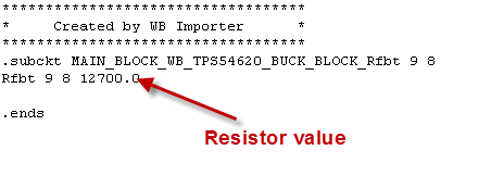
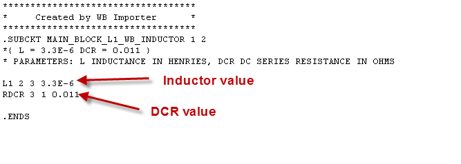
    You can choose how you want to update the models. If you are more comfortable deleting the existing component and replacing it with a standard component, that is fine. You may also edit the existing component .SUBCKT file using the Enter Macro feature and making changes in the actual .SUBCKT statements.

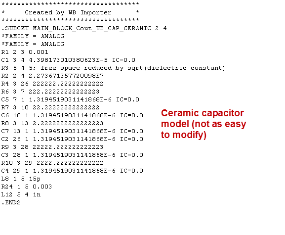
    Here are some examples of what is shown after hitting the Enter Macro button:

    Some of the capacitor models will also be a simpler model that you can simply change the capacitance value.

    You can always simply delete the original component and use the TINA-TI component and its values. For the more complex output cap models this might be your best bet. You can also drop a manufacturer provided model if you wish into the Macro. 

  • Hi, So basically if I change the resistor and inductor values from the macro, it changes them? I changed the inductance value in the macro and I confirmed the changes to the macro when TINA prompted me. But the changed inductance value is not reflected in the displayed value in the simulation itself. Is this intended?

  • Rohit,

    I forgot to mention this. The test that is displayed is simply text that was placed on the schematic when the original macro was made. You would have to update it if you are using the macro. This is due to the way the schematic is exported from WEBENCH® to TINA-TI. TINA-TI does not have any interface for subcircuits to display parameters unless they are specifically defined as .PARAMS in the .SUBCKT. So, since WEBENCH® knows the values, the export simply creates a text tag for each value.

    I should have mentioned that previously. Just click on the text and update it to your new values and the schematic picture will appear correct. Please note that the simulation would ALWAYS be running the values inside the macro, not the values displayed in the text.

  • Hi Brett,
    I did what you suggested. I have replaced the values in the less complex macros, while I replaced the more complex passive components with stock passive components from TINA. I have one more question. In my simulation, there is an input voltage, which steps to a certain value in the beginning and then stays there. I tried to replace it with a voltage generator block in TINA, but the simulation did not run at all. I want to simulate a few step changes after the controller has started, to see its transient response. How to do so? If I have to make changes to the macro itself to include multiple steps, please tell me the script to do so. As of now, the script inside the input voltage macro is:

    ***********************************
    * Created by WB Importer *
    ***********************************
    .SUBCKT INPUT_BLOCK_Vin_WB_STARTUP_VOLTAGE_SOURCE 1 2
    Rsource 3 1 1m
    Vin1 3 2 PULSE 0 22.0 10u 10u
    .ENDS

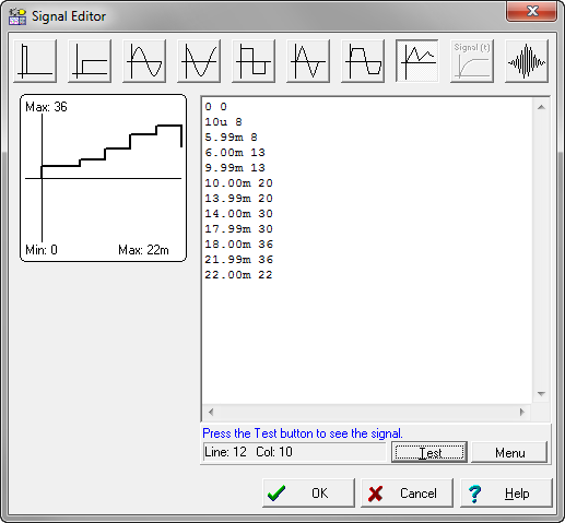
    I can change the value of Vin from 22.0 to any other value to get the desired initial step. Hoever, how to add more step changes to this? Say I want a signal like this:

    Step to 8V at 10us
    Step to 13V at 6 ms
    Step to 20V at 10 ms
    Step to 30V at 14 ms
    Step to 36V at 18 ms
    Step to 22V at 22 ms

    How do I edit the script of the macro to make this happen?

  • Rohit,

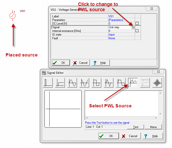
    I would use the TINA-TI voltage generator. I would set it up with the input voltage using the PWL source:

    Enter in the points and test the waveform.

    I am assuming that you want the 10us rise time for each step in voltage.

    I very rarely use the sources provided by WEBENCH® as they are set up for a single input value. Removing the source and adding the TINA-TI source should have NO impact on the simulation. But, you must have the source configured correctly to see the test you want to see. If all of these voltages are within the range of operation of the circuit and IC, you should see the simulation you are desiring.

    If you run into trouble, you can attach the .TSC file and I can look into the issue.

    If you want to use the macro, you would have to change the source to a PWL source and set the voltages and timings on that statement. You can see how to do this in the PSpice PWL source configuration (search on Google for directions). Basically, it uses time/value pairs as shown above in the TINA-TI GUI.

  • Hi Britt, Please see the simulation here:

    dl.dropboxusercontent.com/.../LM5175_sim.TSC

    Whenever I add a voltage generator block instead of the macro block for Vin, I get an error. Please see if you can identify what I am doing wrong. If possible, please add a voltage generator block yourself and give the simulation file to me if it works.

  • Rohit,

    Please see the attached file. It ran fine for me. I have set up the input as shown in the previous post.

    LM5175_sim_up.TSC

    The simulation does take a very long time to run.

  • I don't understand how your edit works and mine does not. This is strange. Well, I will use this.

  • Hi Britt, I ran the simulation and saved the result as a TDR file. How can I view it once I have restarted TINA?
  • Rohit,

    When you start TINA-TI, open the Diagram Window (Tools--> Diagram Window). Then select the File--> Open in that window and navigate to the place where you saved the file.

    It should load into the diagram window as it was saved.