Hi all, I am new to TINA and have been trying to simulate the circuit shown in the Battery Charger document using a LP2951 as a voltage regulator for a single cell Lithium-Ion battery. The problem is that I tried to connect everything as shown but the output voltage is negative when it should be around 5V before diode voltage drop.
It says in the datasheet that to make it an adjustable voltage regulator, the Vtap and Sense pins should be open while it did not say anything about the Error pin (tried connecting it to output and still nothing).
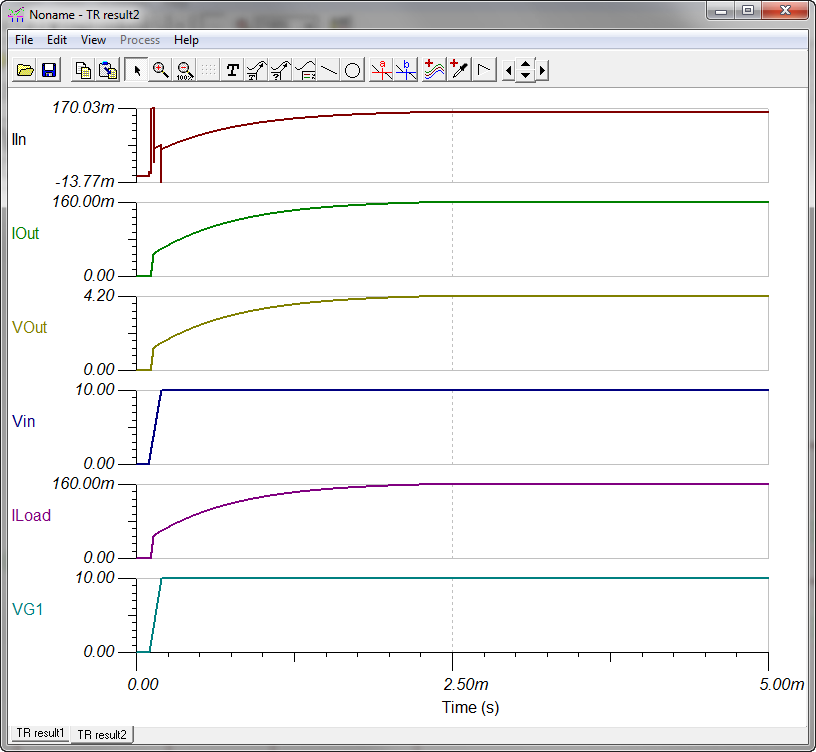
I used the DC analysis to check the simulation.
Tested with Vin=6 V with the circuit shown in the document.
Thank you.