Other Parts Discussed in Thread: TINA-TI, TPS54560
Tool/software: TINA-TI or Spice Models
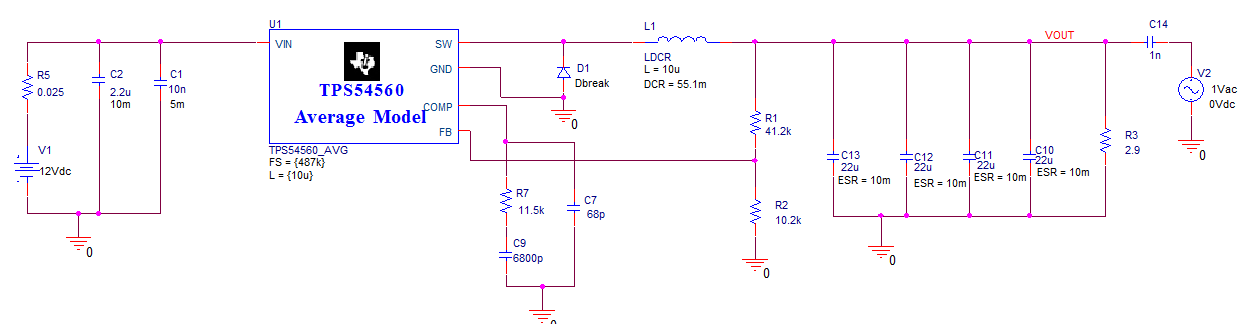
I'm trying to evaluate loop compensation network for TPS54560 using Pspice simulation tool. First I tried by inserting small magnitude ac signal voltage in output loop, getting some weird response, magnitude graph is starting from negative side and approaching zero ( means e2e.docxno 0db crossover, no phase margin).
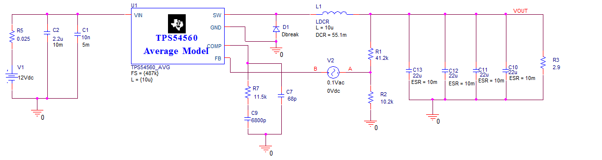
And then I tried by inserting small ac signal voltage in feedback path (as suggested in datasheet), the magnitude plot is starting from zero itself and phase plot is starting from some negative value.
Any help on this?