Other Parts Discussed in Thread: TINA-TI, LM4040
Tool/software: TINA-TI or Spice Models
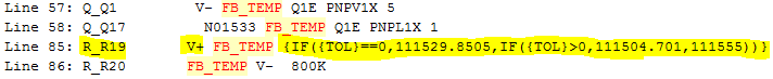
Can someone identity the line in the spice file below where the output voltage is specified/calculated and connected to the cathode? This is the model supplied to National Instruments.
################## SPICE Model ##################
Model ID: LM4040_NA10P0/TI
Model manufacturer: Texas Instruments
Model template: x%p %tK %tA %m
Model data:
* PSpice Model Editor - Version 16.0.0
*$
*LM4040_N
*****************************************************************************
* (C) Copyright 2013 Texas Instruments Incorporated. All rights reserved.
*****************************************************************************
** This model is designed as an aid for customers of Texas Instruments.
** TI and its licensors and suppliers make no warranties, either expressed
** or implied, with respect to this model, including the warranties of
** merchantability or fitness for a particular purpose. The model is
** provided solely on an "as is" basis. The entire risk as to its quality
** and performance is with the customer.
*****************************************************************************
*
** Released by: WEBENCH Design Center,Texas Instruments Inc.
* Part: LM4040_N
* Date: 10APR2013
* Model Type: TRANSIENT
* Simulator: PSPICE
* Simulator Version: 16.0.0
* EVM Order Number: N/A
* EVM Users Guide: N/A
* Datasheet: SNOS633G-May 2004-REVISED July 2012
*
* Model Version: Final 1.00
*
*****************************************************************************
*
* Updates:
*
* Final 1.00
* Release to Web.
*
******************************************************************************
.SUBCKT LM4040_NA10P0/TI V+ V- PARAMS: TOL=0
C_Cstart V- START 400nF TC=0,0
Q_Q22 N03098 N01931 V- NPN1X
Q_Q7 N02184 VC_Q2 N01786 NPN1X
Q_Q12 N02229 N03098 N04190 NPN1X
Q_Q13 N04160 N04160 N04190 NPN1X 10
Q_Q3 VC_Q3 VB_Q3 VE NPN1X 10
Q_Q5 VC_Q3 N01129 N01136 PNPL1X 1.8
Q_Q6 N01129 N01129 N01136 PNPL1X 1.8
C_C3 N03098 N01136 3pF TC=0,0
Q_Q23 N01136 N01136 N08107 NPN1X
R_R10 N01129 N01786 60K TC=0,0
Q_Q15 N04160 N02229 N01136 PNPL1X 10
R_R1toR5 N07686 N01136 30.5K TC=0,0
R_R15 N01931 Q20B 66K TC=0,0
Q_Q14 N02229 N02229 N01136 PNPL1X 1
Q_Q20 N01533 Q20B V- NPN1X
R_R6 VB_Q2 N07686 20K TC=0,0
C_Cx V- N01136 1pF TC=0,0
C_C2 VC_Q3 N02514 6pF TC=0,0
E_Estart N30465 V- VALUE { max(0.4*(1-V(VB_Q2, VB_Q3)/.05), 0)+V(Q20B)
+ }
Q_Q1 V- FB_TEMP Q1E PNPV1X 5
Q_Q17 N01533 FB_TEMP Q1E PNPL1X 1
R_Rx6 V+ N01136 1000 TC=0,0
Q_Q19 Q20B VE N08426 PNPL1X 1
R_R8 Q1E VB_Q3 45K TC=0,0
Q_Q16 N01136 N04160 V- NPN1X 10
Q_Q4 VC_Q2 N01129 N01136 PNPL1X 1.8
R_R13 Q20B N01533 40K TC=0,0
R_Rstart0 START N30465 225 TC=0,0
R_R11 N02514 N02184 100K TC=0,0
R_R14 N01755 V- 3.3K TC=0,0
Q_Q11 N03098 N02514 N01136 PNPL1X 1.8
Q_Q21 N01786 Q20B N01755 NPN1X 6.75
Q_Q24 N01136 N07686 N08116 NPN1X
Q_Q8 N02514 VC_Q3 N01786 NPN1X
Q_Q2 VC_Q2 VB_Q2 VE NPN1X
Q_Q10 N02514 N02184 N01136 PNPL1X 3.1
Q_Q9 N02184 N02184 N01136 PNPL1X 3.1
R_R18 Q1E N08116 69K TC=0,0
R_R59 N01136 N08426 51K TC=0,0
R_R12 N01505 V- 6K TC=0,0
L_Lx1 N01136 V+ 10uH
R_R16 N04190 V- 1K TC=0,0
Q_Q18 VE Q20B N01505 NPN1X
R_Rstart1 Q20B START 20K TC=0,0
R_R17 N08116 N08107 130k TC=0,0
R_R7 VB_Q3 VB_Q2 10K TC=0,0
C_C1 VC_Q2 N03098 3pF TC=0,0
R_R19 V+ FB_TEMP {IF({TOL}==0,111529.8505,IF({TOL}>0,111504.701,111555))}
R_R20 FB_TEMP V- 800K
.model NPN1X NPN Is=13.84e-18 Bf=130 TR=8ns
.model PNPV1X PNP Is=261.8e-18 Bf=222
.model PNPL1X PNP Is=48e-18 Bf=63
.model Menable NMOS LEVEL 1
+ VTO 0
+ KP 20.000000E-06
+ PHI 0.6
+ IS 10.000000E-15
+ PB .8
+ PBSW .8
*+ UCRIT 10.000000E+03
*+ DIOMOD 1
*+ VDD 5
*+ XPART 0
*
*
.model Dideal D Is=0.001p N=0.01 Rs=0 Ikf=0 Xti=2 Eg=1.11 Cjo=0
+ M=0.33 Vj=1 Fc=0.5 Isr=0.1n Nr=2 Bv=75 Ibv=1e-10 Tt=0
*
*
.ENDS LM4040_NA10P0/TI
*$
I want to modify the model to add a tolerance and tempco by operating on the derived output value.
R Phillips