


Part Number: UCC28950
Other Parts Discussed in Thread: TINA-TI,
Tool/software: TINA-TI or Spice Models
Hello All,
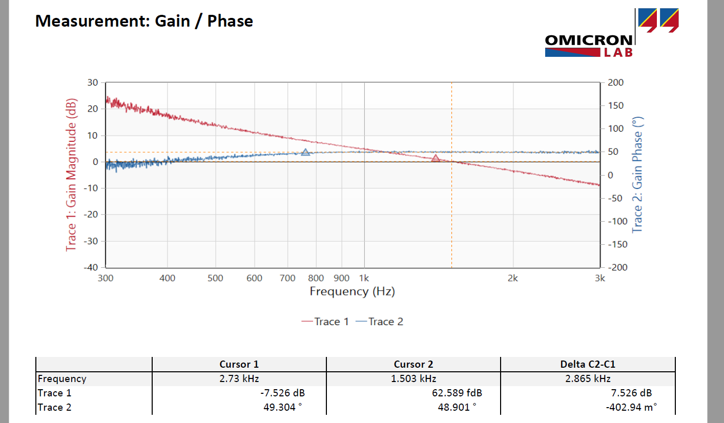
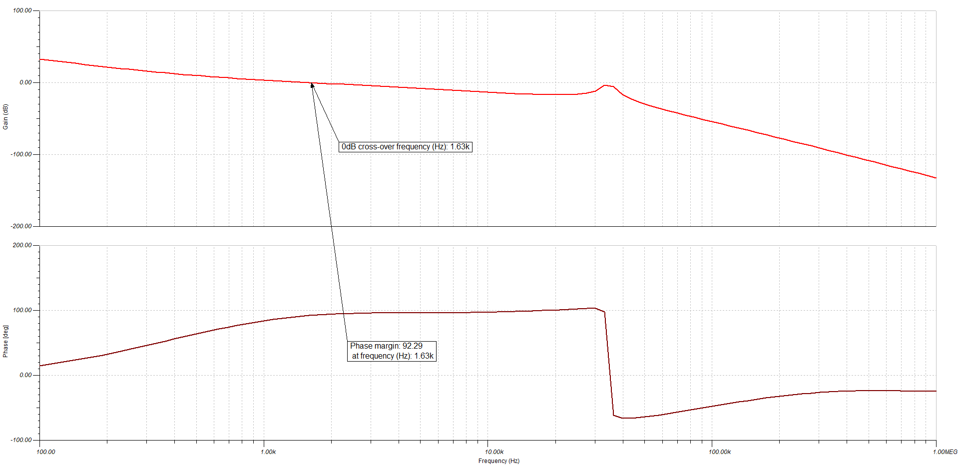
I am designing a FBZVT DC-DC based on the UCC28950. Currently, I am struggling with the loop gain compensation design. The converter is up and running and appears stable. The problem is that I can't get my phase margin and gain margin measurement on my BODE 100 analyzer to match the simulation results of the current mode average model supplied in the TINA Spice program. The crossover frequency matches pretty well, however the measured phase margin on the BODE analyzer is 50 degrees, whereas the simulation gives a phase margin of approximately 90 degrees. I am measuring at 1/2 load.
I played with the inductor values and capacitor ESR values to see if I had a zero in the simulation that either didn't actually exist, or was out of the frequency band of the loop gain, but no help. So I am now grinding through the FBZVT current mode model analysis trying to find where the extra forty degrees of phase margin comes from.
My question is the following: Does the TINA spice average current model take into account the effect of the leakage inductor and the subsequent lost duty cycle and duty cycle delay? I notice that in the ucc28950 the compensation design is based on a simple average current mode model, which is incorrect.What is the impact of this simplification? Does the TINA SPICE model follow the user guide?
I need to know the answer to this question to help me determine whether the phase margin mismatch is due to the BODE 100, noise in test set-up, or the way I am measuring it, or if the simplified current mode model predicts too high a phase margin. If I can match my measurements to the SPICE models, I can optimize the compensation design.
TINA SPICE Current Mode Average Model

Bode Measurement is below, follow trace 2.
The TINA Spice simulation result is below:
Thanks,
Chuck Sampson