This thread has been locked.

If you have a related question, please click the "Ask a related question" button in the top right corner. The newly created question will be automatically linked to this question.

TIDA-00217: Gets stucked at while(!(UCB0IFG & UCTXIFG0));

Part Number: TIDA-00217
Other Parts Discussed in Thread: MSP-FET, , TMP103, MSP430FR5969, TMP100

Hello,

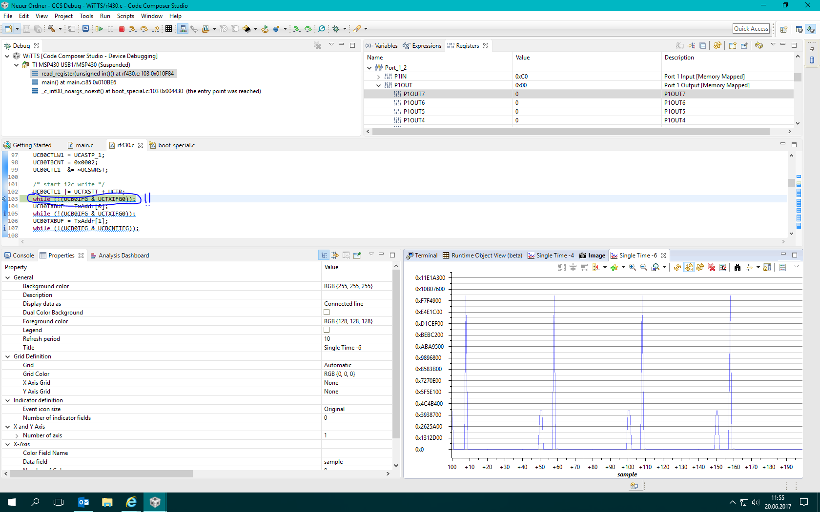
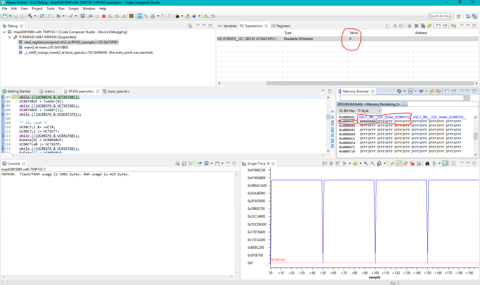
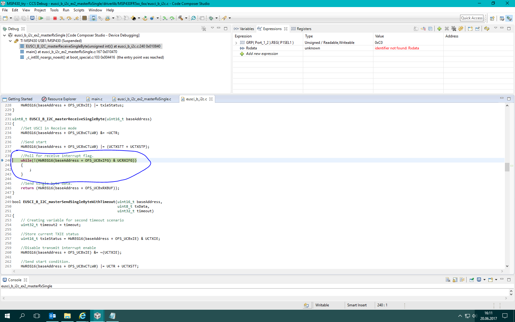
I have fabricated the TIDA-00217 exactly as mentioned in the reference designs. But, when I run the debug the program using MSP-FET it gets stuck in this line which has

while(!(UCB0IFG & UCTXIFG0));


It seems like my I2C communication is not working with RF430 and TMP103.

I have cross checked my I2C Pins. P1.6 and P1.7 are connected to B0_SCL and B0_SDA. The chip used in TIDA-00217 is MSP430FR5969.


Should I check anything else apart from the Pins? I had tried bypassing the RF430 module. The communication doesnt work even with the TMP103 sensor.


What could be the issue?


Thank you in advance.

  • Hello Manoj,

    Please confirm that P1.6 is SDA and P1.7 is SCL, and that they are both pulled up through a 4.75 kOhm resistor to Vcc. Make sure that each device is being powered by 3.3 V and has proper GND connections. Are E0/1/2 grounded by your design? Can you provided oscilloscope or logic analyzer images of the I2C lines?

    Regards,
    Ryan
  • Hello,

    Yes, I have fabricated the PCB according to the reference designs given in

    www.ti.com/.../tida-00217.

    I have also checked the Connections again.  P1.6, P1.7 of MSP430FR5969, 11, 12 Pins of RF430 and B2, B1 of Local Temperature sensor are connected to b0_SCl and b0_SDA as mentioned in the reference design.

    And also the resistance between Vcc and each of SCL and SDA is around 4.5kOhms.

    Sorry, if I didnt not give the same logic analyzer values. I am new to cc Studio. But I set the starting address of the graph as 0x0200. And there is no Change in P1OUT values. Anything else I could check?

  • Hi Manoj,

    You are stuck in this while loop because neither slave device is acknowledging the start condition and slave address sent by the MSP430FR5969, which could be further verified by evaluating the UCNACKIFG. You will need to find the cause of this, whether it is the wrong slave address, faulty I2C bus, or improperly connected/powered slave devices. Evaluating the P1OUT register does you no good since the pins are set to eUSCI functionality.

    Regards,
    Ryan
  • 1) The slave address of RF430 is 0x0028 and TMP103 is 0x0070. The Firmware is not modified at all. It is also downloaded from TIDA 00217 reference Firmware.

    2) I have monitored the UCNACKIFG bit as you told. I have set the graph starting address as 0x00066c which is USCI_B0_I2CMode_UCB0IFG Register. But I notice that the bit remains to be Zero always from the debug window.

    Here is the Monitoring graph.

    Another small question:- Is there anyway to Monitor just one bit instead of the entire Register?

  • Why is the I2c bus configured to transmit mode in TMP103 mode?  The below is the Code snippet from TMP103.c

       /* Software reset enabled */

       UCB0CTL1 |= UCSWRST;

       /* I2C mode, Master mode, sync, transmitter */

       UCB0CTLW0 |= UCMODE_3  + UCMST + UCSYNC + UCTR;   WHY?? Isn't TM103 providing values to the MSP430?

       /* SMCLK = 8MHz */

       UCB0CTLW0 |= UCSSEL_2;

       /* Baudrate = SMLK/40 = 200kHz */

       UCB0BRW = 30;

    I have also tried the example peripheral program eusci_b_i2c_ex2_masterRxSingle.c. Master program for single slave. I have changed the slave address to TMP103 address 0x28

    #define SLAVE_ADDRESS 0x28 

    uint8_t RXData;

    void main(void)

    {

    //Stop WDT

    WDT_A_hold(WDT_A_BASE);

    //Set DCO frequency to 1MHz

    CS_setDCOFreq(CS_DCORSEL_0,CS_DCOFSEL_0);

    //Set ACLK = VLO with frequency divider of 1

    CS_initClockSignal(CS_ACLK,CS_VLOCLK_SELECT,CS_CLOCK_DIVIDER_1);

    //Set SMCLK = DCO with frequency divider of 1

    CS_initClockSignal(CS_SMCLK,CS_DCOCLK_SELECT,CS_CLOCK_DIVIDER_1);

    //Set MCLK = DCO with frequency divider of 1

    CS_initClockSignal(CS_MCLK,CS_DCOCLK_SELECT,CS_CLOCK_DIVIDER_1);

    // Configure Pins for I2C

    //Set P1.6 and P1.7 as Secondary Module Function Input.

    /*

    * Select Port 1

    * Set Pin 6, 7 to input Secondary Module Function, (UCB0SIMO/UCB0SDA, UCB0SOMI/UCB0SCL).

    */

    GPIO_setAsPeripheralModuleFunctionInputPin(

    GPIO_PORT_P1,

    GPIO_PIN6 + GPIO_PIN7,

    GPIO_SECONDARY_MODULE_FUNCTION

    );

    //Set P1.0 as an output pin.

    /*

    * Select Port 1

    * Set Pin 0 as output

    */

    GPIO_setAsOutputPin(

    GPIO_PORT_P1,

    GPIO_PIN0

    );

    /*

    * Disable the GPIO power-on default high-impedance mode to activate

    * previously configured port settings

    */

    PMM_unlockLPM5();

    EUSCI_B_I2C_initMasterParam param = {0};

    param.selectClockSource = EUSCI_B_I2C_CLOCKSOURCE_SMCLK;

    param.i2cClk = CS_getSMCLK();

    param.dataRate = EUSCI_B_I2C_SET_DATA_RATE_400KBPS;

    param.byteCounterThreshold = 1;

    param.autoSTOPGeneration =

    EUSCI_B_I2C_SEND_STOP_AUTOMATICALLY_ON_BYTECOUNT_THRESHOLD;

    EUSCI_B_I2C_initMaster(EUSCI_B0_BASE, &param);

    //Specify slave address

    EUSCI_B_I2C_setSlaveAddress(EUSCI_B0_BASE,

    0x0070

    );

    //Set Master in receive mode

    EUSCI_B_I2C_setMode(EUSCI_B0_BASE,

    EUSCI_B_I2C_RECEIVE_MODE

    );

    //Enable I2C Module to start operations

    EUSCI_B_I2C_enable(EUSCI_B0_BASE);

    EUSCI_B_I2C_clearInterrupt(EUSCI_B0_BASE,

    EUSCI_B_I2C_RECEIVE_INTERRUPT0 +

    EUSCI_B_I2C_BYTE_COUNTER_INTERRUPT

    );

    //Enable master Receive interrupt

    EUSCI_B_I2C_enableInterrupt(EUSCI_B0_BASE,

    EUSCI_B_I2C_RECEIVE_INTERRUPT0 +

    EUSCI_B_I2C_BYTE_COUNTER_INTERRUPT

    );

    while(1)

    {

    __delay_cycles(2000);

    // I2C start condition

    RXData = EUSCI_B_I2C_masterReceiveSingleByte(EUSCI_B0_BASE);

    }

    }

    It gets stuck in the Poll for recieve Interrupt flag!

    Summary:-  I want to know why the Firmware has configured to Transmit mode. If I am still polling in the example program what does it mean?

    is there a simple program which Interfaces MSP430FR5969 and TMP103 just to recieve temperature?

  • The firmware is configured to transmit mode in accordance with the sequence shown in Figure 3 of the TMP103 datasheet, where the pointer register byte is first sent to the slave device before the data byte register is read.  In the Temp_Read function you can see that TEMP_REG is sent, then the UCTR bit is cleared, and a repeated start is followed with a data read.  This sequence follows the standard I2C protocol and your code example might need to do likewise in order to function properly.  The closest code example I know of uses a MSP430G2xx3 and TMP100.  If you are using a TMP103x variant other than "A" then your slave address will be incorrect.

    msp430g2xx3_uscib0_i2c_01.c
    /* --COPYRIGHT--,BSD_EX
     * Copyright (c) 2012, Texas Instruments Incorporated
     * All rights reserved.
     *
     * Redistribution and use in source and binary forms, with or without
     * modification, are permitted provided that the following conditions
     * are met:
     *
     * *  Redistributions of source code must retain the above copyright
     *    notice, this list of conditions and the following disclaimer.
     *
     * *  Redistributions in binary form must reproduce the above copyright
     *    notice, this list of conditions and the following disclaimer in the
     *    documentation and/or other materials provided with the distribution.
     *
     * *  Neither the name of Texas Instruments Incorporated nor the names of
     *    its contributors may be used to endorse or promote products derived
     *    from this software without specific prior written permission.
     *
     * THIS SOFTWARE IS PROVIDED BY THE COPYRIGHT HOLDERS AND CONTRIBUTORS "AS IS"
     * AND ANY EXPRESS OR IMPLIED WARRANTIES, INCLUDING, BUT NOT LIMITED TO,
     * THE IMPLIED WARRANTIES OF MERCHANTABILITY AND FITNESS FOR A PARTICULAR
     * PURPOSE ARE DISCLAIMED. IN NO EVENT SHALL THE COPYRIGHT OWNER OR
     * CONTRIBUTORS BE LIABLE FOR ANY DIRECT, INDIRECT, INCIDENTAL, SPECIAL,
     * EXEMPLARY, OR CONSEQUENTIAL DAMAGES (INCLUDING, BUT NOT LIMITED TO,
     * PROCUREMENT OF SUBSTITUTE GOODS OR SERVICES; LOSS OF USE, DATA, OR PROFITS;
     * OR BUSINESS INTERRUPTION) HOWEVER CAUSED AND ON ANY THEORY OF LIABILITY,
     * WHETHER IN CONTRACT, STRICT LIABILITY, OR TORT (INCLUDING NEGLIGENCE OR
     * OTHERWISE) ARISING IN ANY WAY OUT OF THE USE OF THIS SOFTWARE,
     * EVEN IF ADVISED OF THE POSSIBILITY OF SUCH DAMAGE.
     *
     *******************************************************************************
     * 
     *                       MSP430 CODE EXAMPLE DISCLAIMER
     *
     * MSP430 code examples are self-contained low-level programs that typically
     * demonstrate a single peripheral function or device feature in a highly
     * concise manner. For this the code may rely on the device's power-on default
     * register values and settings such as the clock configuration and care must
     * be taken when combining code from several examples to avoid potential side
     * effects. Also see www.ti.com/grace for a GUI- and www.ti.com/msp430ware
     * for an API functional library-approach to peripheral configuration.
     *
     * --/COPYRIGHT--*/
    //******************************************************************************
    //  MSP430G2xx3 Demo - USCI_B0 I2C Master to TMP100, Set P1.0 if Temp > 28C
    //
    //  Description: I2C interface to TMP100 temperature sensor in 9-bit mode.
    //  Timer_A CCR0 interrupt is used to wake up and read the two bytes of
    //  the TMP100 temperature register every 62ms. If the temperature is greater
    //  than 28C, P1.0 is set, else reset. CPU is operated in LPM0. I2C speed
    //  is ~100kHz.
    //  ACLK = n/a, MCLK = SMCLK = TACLK = BRCLK = default DCO = ~1.2MHz
    //
    //         /|\           /|\ /|\
    //          |   TMP100   10k 10k     MSP430G2xx3
    //          |   -------   |   |   -------------------
    //          +--|Vcc SDA|<-|---+->|P1.7/UCB0SDA    XIN|-
    //          |  |       |  |      |                   |
    //          +--|A1,A0  |  |      |               XOUT|-
    //             |       |  |      |                   |
    //          +--|Vss SCL|<-+------|P1.6/UCB0SCL   P1.0|---> LED
    //         \|/  -------          |                   |
    //
    //  D. Dang
    //  Texas Instruments Inc.
    //  February 2011
    //   Built with CCS Version 4.2.0 and IAR Embedded Workbench Version: 5.10
    //******************************************************************************
    #include <msp430.h>
    
    unsigned int RxByteCtr;
    unsigned int RxWord;
    
    int main(void)
    {
      WDTCTL = WDTPW + WDTHOLD;                 // Stop WDT
      P1DIR |= BIT0;                            // P1.0 output
      P1SEL |= BIT6 + BIT7;                     // Assign I2C pins to USCI_B0
      P1SEL2|= BIT6 + BIT7;                     // Assign I2C pins to USCI_B0
      UCB0CTL1 |= UCSWRST;                      // Enable SW reset
      UCB0CTL0 = UCMST + UCMODE_3 + UCSYNC;     // I2C Master, synchronous mode
      UCB0CTL1 = UCSSEL_2 + UCSWRST;            // Use SMCLK, keep SW reset
      UCB0BR0 = 12;                             // fSCL = SMCLK/12 = ~100kHz
      UCB0BR1 = 0;
      UCB0I2CSA = 0x4e;                         // Set slave address
      UCB0CTL1 &= ~UCSWRST;                     // Clear SW reset, resume operation
      IE2 |= UCB0RXIE;                          // Enable RX interrupt
      TACTL = TASSEL_2 + MC_2;                  // SMCLK, contmode
    
      while (1)
      {
        RxByteCtr = 2;                          // Load RX byte counter
        UCB0CTL1 |= UCTXSTT;                    // I2C start condition
        __bis_SR_register(CPUOFF + GIE);        // Enter LPM0, enable interrupts
                                                // Remain in LPM0 until all data
                                                // is RX'd
    
        if (RxWord < 0x1d00)                    // >28C?
          P1OUT &= ~0x01;                       // No, P1.0 = 0
        else
          P1OUT |= 0x01;                        // Yes, P1.0 = 1
    
        __disable_interrupt();
        TACCTL0 |= CCIE;                        // TACCR0 interrupt enabled
        __bis_SR_register(CPUOFF + GIE);        // Enter LPM0, enable interrupts
                                                // Remain in LPM0 until TACCR0
                                                // interrupt occurs
        TACCTL0 &= ~CCIE;                       // TACCR0 interrupt disabled
      }
    }
    
    #if defined(__TI_COMPILER_VERSION__) || defined(__IAR_SYSTEMS_ICC__)
    #pragma vector = TIMER0_A0_VECTOR
    __interrupt void TA0_ISR(void)
    #elif defined(__GNUC__)
    void __attribute__ ((interrupt(TIMER0_A0_VECTOR))) TA0_ISR (void)
    #else
    #error Compiler not supported!
    #endif
    {
      __bic_SR_register_on_exit(CPUOFF);        // Exit LPM0
    }
    
    // The USCIAB0TX_ISR is structured such that it can be used to receive any
    // 2+ number of bytes by pre-loading RxByteCtr with the byte count.
    #if defined(__TI_COMPILER_VERSION__) || defined(__IAR_SYSTEMS_ICC__)
    #pragma vector = USCIAB0TX_VECTOR
    __interrupt void USCIAB0TX_ISR(void)
    #elif defined(__GNUC__)
    void __attribute__ ((interrupt(USCIAB0TX_VECTOR))) USCIAB0TX_ISR (void)
    #else
    #error Compiler not supported!
    #endif
    {
      RxByteCtr--;                              // Decrement RX byte counter
    
      if (RxByteCtr)
      {
        RxWord = (unsigned int)UCB0RXBUF << 8;  // Get received byte
        if (RxByteCtr == 1)                     // Only one byte left?
          UCB0CTL1 |= UCTXSTP;                  // Generate I2C stop condition
      }
      else
      {
        RxWord |= UCB0RXBUF;                    // Get final received byte,
                                                // Combine MSB and LSB
        __bic_SR_register_on_exit(CPUOFF);      // Exit LPM0
      }
    }


    Regards, Ryan

  • Thank you for the Explanation. Now I understood why the I2C bus is configured in the transmit mode. So I tried reading the temperature data from TMP103 by using

    Temp_I2C_Init(); and Temp_Read() functions from tmp103.c. But ist again getting stuck at

    while(!(UCB0IFG & UCTXIFG0));

    UCB0TXBUF = TEMP_REG;

    The TEMP_REG Code is not able to get transmited.

    Here is my modified Code. Only the ones in main() are modified.


    void main (void)

    {

    volatile unsigned int test = 0;

    volatile unsigned int flags = 0;

    //unsigned char read_data[200];

    MSP430_Init();

    Temp_I2C_Init();


    while (1)

    {

    Low_Power_Delay_ms(1);

    Temp_Read();

    Low_Power_Delay_ms(4000); // 4 second delay before next Temp reading.

    while(!(Read_Register(STATUS_REG) & READY)); //wait until READY bit has been set

    }

    }

    The Code gets stuck at Temp_Read() function.


    Is there any function just to check whether the I2C slave is present or not. Like the function in  TI_USCI_I2C_master.c file . TI_USCI_I2C_slave_present(). I couldnt find any I2C function in MSP430FR5969 which tells whether the slave is present or not. 

    With this function, I could just check whether my temperature sensor is damaged. 


  • TI_USCI_I2C_slave_present() simply sends a start, slave address, and stop condition while evaluating the UCNACKIFG to see if the slave acknowledged the address or not, you could replicate this easily enough if desired.

    Regards,
    Ryan
  • Hello Ryan,

    Sorry for replying late. I have fabricated new TIDA 00217 boards and ran the program. It worked this time. The previous issue would have been due to improper Connections between MSP 430 and other components.

    Now I have one more doubt regarding the NFC-Reader. Which Reader would be capable of reading Type 4b tags. Because RF430CL330 is NFC type 4B Transponder. Do you think explore-nfc from nxp can do that?

    I have the Firmware for reading Type 3B NDEF Messages. Do you think the same Firmware can be used to read NDEF messgaes of RF430CL330 Transponder?

    Thank you in advance.

  • Hello Manoj,

    I'm glad to hear that you've made some progress. I don't have enough knowledge of NFC technology to answer your follow-up question, you should refer to the NFC/RFID Forum.

    Regards,
    Ryan