This thread has been locked.

If you have a related question, please click the "Ask a related question" button in the top right corner. The newly created question will be automatically linked to this question.

TINA/Spice/TINA-TI: Level Shifter Circuit

Part Number: TINA-TI

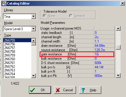
Tool/software: TINA-TI or Spice Models

Hey,

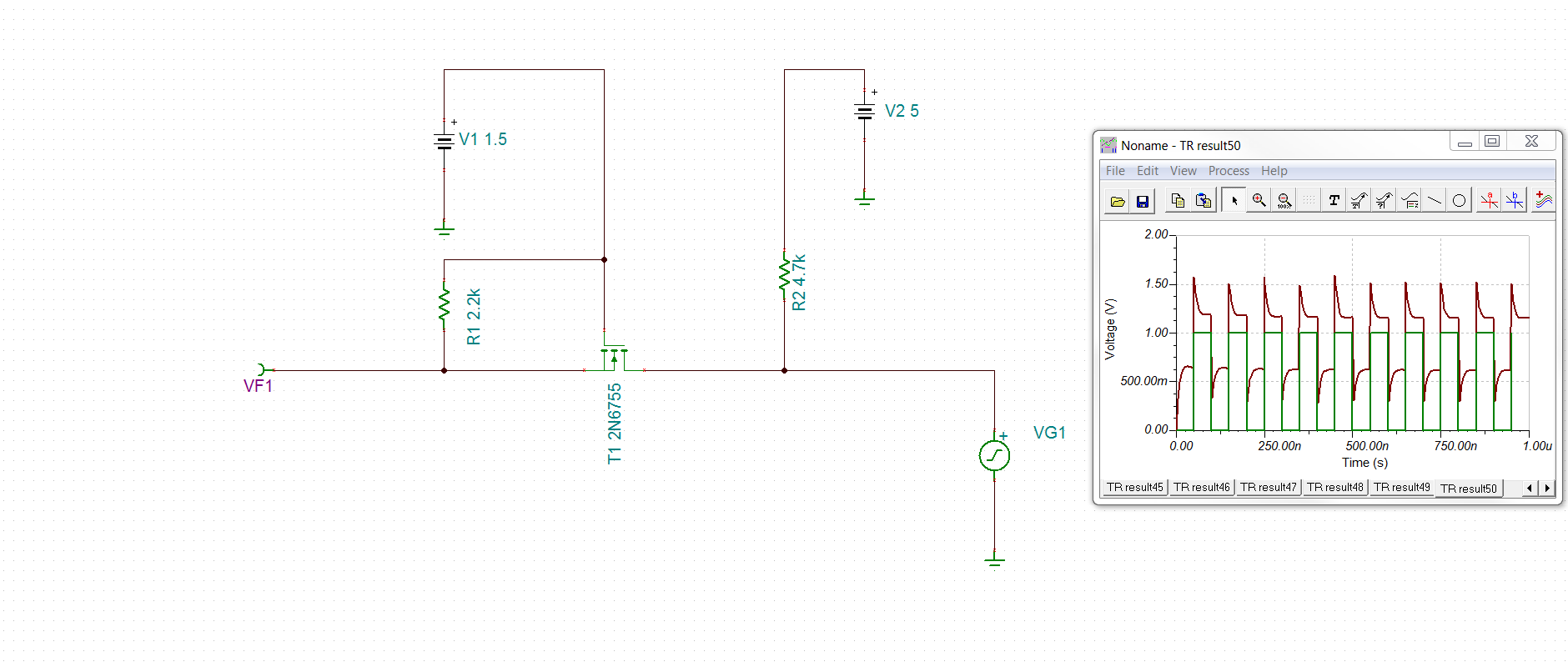
I am trying to create a simple level shifter circuit that has a pulse signal as shown in green on the TR analysis which corresponds to VG1. VG1 pulse alternates between high and low every 50ns. However, a proper level shifter matches the highs and lows on both the 5v and 1.5V. However, VF1 (red signal) shows a decaying signal. The ideal red signal is a pulse with a high of 1.5V and a low of )v alternating every 50 ns. Can anyone help to see what I'm doing wrong? 

Thanks


  • Hi Mani,

    Increasing the GATE resistance of the MOSFET resolves the issue. Below is the simulation result.

    To change the value of MOSFET GATE resistance follow the below steps.

    1. Double click on the MOSFET symbol. A window will open.

    2. Click on the button as shown below


    A window will open.

    3. Change the GATE resistance value to 1G as shown below 

    Thanks & Regards,

    Arpan Gupta

  • Thanks Arpan. 

    However, I think my issue is somehow with generating the pulse signal. I'm not sure how to do a pulse signal and I'm still getting an incorrect result. Can you please check my file and help me out? 

    LevelShifter.TSC

  • Hi Mani,

    Could you kindly clarify what input signal you want to provide to the level shifter circuit? Also what output signal you are expecting? (Please provide us the voltage levels, time period of the input and output signals)

    Thanks & Regards,
    Arpan Gupta