This thread has been locked.

If you have a related question, please click the "Ask a related question" button in the top right corner. The newly created question will be automatically linked to this question.

TINA/Spice/CSD15380F3: How to simulate rise/fall time of FET

Part Number: CSD15380F3
Other Parts Discussed in Thread: TINA-TI,

Tool/software: TINA-TI or Spice Models

Hi,

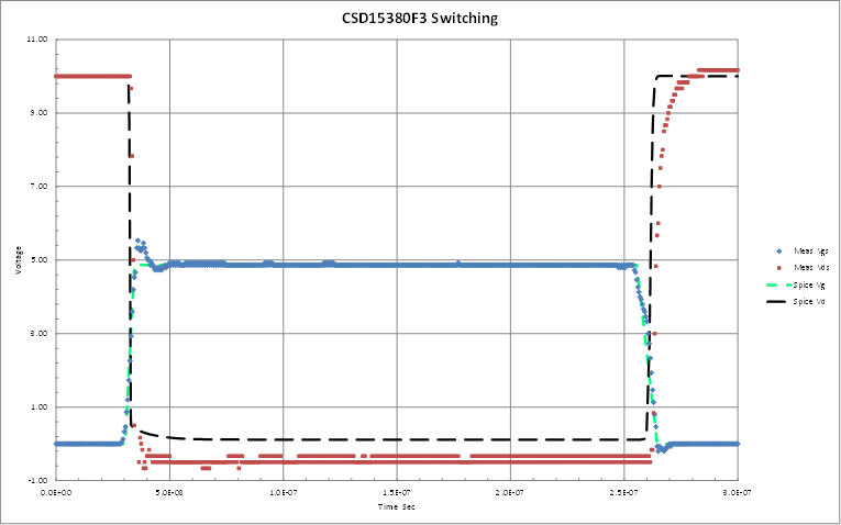
I simualted the rise/fall time of FET(CSD15380F3). But the simulated results and datasheet specs are different.

In the datasheet, the test conditions are Vds=10V, Vgs=4.5V, Rg=0Ohm, Ids=0.1A. And the rise time is 1ns and fall time is 7ns. 

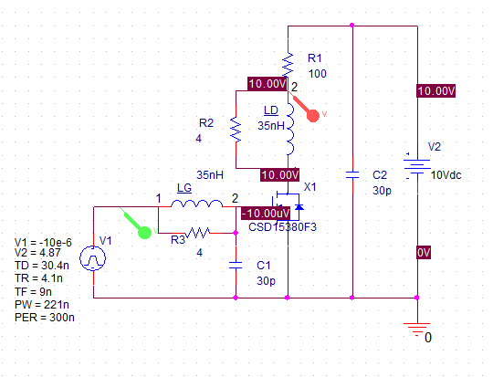
Therefore, in the simulation, I connected 0Ohm and 100Ohm to the gate and drain of FET, respectively. Vds is 10V and Vgs is 4.5V pulse.(I set the rise/fall time of Vgs is 1ps.)

But in my simulation results, rise time is 1.6ns and fall time is 1.6ns.

What is wrong in my simulation setting?

How to simulate the rise and fall time of FET?


  • One of our team member will look into this, but it will be after new year's holiday.

    Happy New Year!
  • Hi Dohan

    From our MOSFET SPICE model creator regarding rise and fall time:

    This device is designed for load switch applications requiring very small loading capacitance (Ciss < 10pF).  The switching characteristics were not modeled.  However, the measured switching waveform with 100 ohm load resistance is shown below.  The problem we have is that the board used to measure the switching has real inductance and more parasitic capacitance than does the device!  So adjusting the applied gate pulse characteristics in spice (trise=4.1n; tfall=9n) and adding in some L and C for measurement board, we have the measured versus modeled waveform shown below.

    The modeled trise time is reasonably close, while the modeled fall time still shows some error.  I’m not sure how much of the error is due to measurement and how much is real.  Since the model includes fairly accurate representations of Ciss/Coss/Crss and Vt, I suspect the error has more to do with measurement board parasitics than the device model.

    Also, the datasheet rise/fall/delay times do NOT take into account the board parasitics.  So the datasheet gives rise & fall times that are pessimistic. 

    Here is the spice circuit used.  The parasitic C’s and L’s are guestimates.  The Rload = 100 ohms was used in measurement.

    Thanks

    Ranjani