This thread has been locked.

If you have a related question, please click the "Ask a related question" button in the top right corner. The newly created question will be automatically linked to this question.

WEBENCH® Tools/TPS54360-Q1: OpVal & bode plot cross over frequency not matching after customizing components.

Part Number: TPS54360-Q1

Tool/software: WEBENCH® Design Tools

Hi TI Support,

I happened to create 15 to 3.4V design with Iout=1.5A. I followed the datasheet design steps. Most components are customized including compensating components. Design seems to be stable but cross over freq. in bode plots is not matching to Op Val. If anybody can provide email ID, I can share the design for your review.

Please advice.

Thanks,

jagdish

  • Hi Jagdish, and happy holidays.

    If you are making large scale changes to the schematic, I recommend using the "Re-Comp" function in Webench to recalculate the compensation. There are options for manual and automatic re-compensation and you can update your design as well.
  • Hi John,

    Thanks & happy holiday to you also.

    BTW, I tried compensating manually with same components. Calculated values in Re-comp shows cross over freq. of 22.7K but bode plot gives near 13.7K. Later I tried Re-comp with Auto option, with that compensating components values changed & calculated freq was 21.6K but again bode plot shows 13.7K cross over freq. Design seems to be stable but my only query is why simulation fails to results achieve near calculation.

    The other query gets generated is which results are to be believed going by datasheet (Manual Re-comp) or by bode plot.

    Thanks,
    jagdish
  • Hi John,

    I also noticed output load resistor in startup & Input transient simulation doesn't get enabled & hence I am unable to run these simulations. Can you also please look into this. I will appreciate if you could share email ID so you can look into this.

    Regards,
    jagdish
  • Jagdish,

    This is really more of a Webench software question rather than a TPS54360-Q1 issue. I will move this to the Webench forum. I will take a look at it though. You can email me at j(dash)tucker(at)ti(dot)com.
  • Hi John,

    Thanks for moving query to pertaining forum. I have shared the design at said email ID & will await further comments on this.

    Regards,
    jagdish
  • Jagdish,

    I check the design you forwarded. The crossover frequency in "Op Vals" table matches the plot in the "Charts" tab at 22.5 kHz. Am I missing something here?
  • Hi John,

    As mentioned in thread above, I was talking about difference in cross over freq. between Op Vals & "Bode Plots". Please look into that.

    Regards,
    jagdish
  • Jagdish,

    In the design you forwarded, they were identical.
  • Hi John,

    Did you check there in "bode plot simulations". In Bode Plot simulation it shows 13.7K. "Chart" section is different data, I specifically ask bode plot simulations. Please confirm as I checked today in morning & results are differing.

    Regards,
    jagdish
  • OK, I see that. I will forward this to the Webench team. Please be aware we are on holiday, so you may not get a response from them until after the new year.
  • Hi John,

    Thanks for taking out your time even in holidays, appreciate that. I will await response from Webench team.

    Regards,
    jagdish
  • Hi Jagdish,

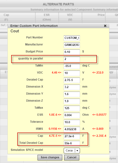
    Thanks for the question. This has to do with the output cap being a custom cap and how sim and opvals are handling the capacitor's derated value for internal calculations. Both bode plot sims and opvals should be using the "Total Derated Cap" value that you observe when you set the custom cap properties ("Select Alternate part" -> "Create a custom part"). Currently, for your design, the total derated cap value is set to 55uF which probably got carried over from the default design. However, the bode plot sims seem to be using the nominal cap of 2 x 47uF = 94uF for simulation causing this discrepancy. I will need to look at it further to see why this is happening.

    In the meanwhile, to get around this, you can set the "Total Derated Cap" to be the derated value of the custom cap you will use on the board. "Cap" = "Total Derated Cap"/"quantity in parallel". So, if you are using a 55uF value for Total Derated Cap and 2 caps in parallel, use 27.5uF for the Cap value.  This way both bode plot sims and opval calculations will use same cap value internally. The "Re-Comp" feature uses the "Total Derated Cap" value and you can see this under "Power stage components" tab where Cout value is shown. 

    Here is a link to the updated design from you with 2 caps in parallel and using a total derated cap of 55uF and cap value of 27.5uF (as an example):

    https://webench.ti.com/appinfo/webench/scripts/SDP.cgi?ID=BCA49151749956AD

    You can change the values as required by clicking on "Select Alternate Part" -> "Create a custom part". Please let me know if you have any questions. Also, if you would like me to change the derated value from 27.5uF to a different value, feel free to let me know and I can send an updated design link here for you.

    Regards,

    Amod

  • Hi Amod,

    Thanks for pointing to this discrepancy, I shall check the design shared by you & let you if any further questions.

    Regards,
    jagdish
  • Hi Amod,

    I happen to check the design shared by you. Bode plot simulation cross freq. do match with OpVals but still I can't see resistor value change for "Input transient" & "Start up" simulations, so unable to do those simulations. Can you please look into these issues.

    Regards,
    jagdish
  • Jagdish,

    Sorry I missed that issue. I refreshed the design and also ran the simulations here in this design: https://webench.ti.com/appinfo/webench/scripts/SDP.cgi?ID=497642EB30C2B944 It might have been an issue with a corrupt design while making all the custom changes. Please let me know if you are able to simulate input transient and startup sims now.

    Regards,

    Amod

  • Hi Amod,

    Thanks for sharing the refreshed design. I checked the design shared by you, startup & input transient are working fine. Just a question, I tried refreshing design by closing & re-opening design, changing inductor/ capacitor ESR slightly but design was not getting refreshed even it showed on the screen. May I know how did you refreshed the design?

    Regards,
    jagdish
  • Hi Jagdish,

    I created a new design with your specs and matched each component one by one with your shared design.  

    Regards,
    Amod

  • Hi Amod,

    Thanks for the clarification.

    Regards,
    jagdish