This thread has been locked.

If you have a related question, please click the "Ask a related question" button in the top right corner. The newly created question will be automatically linked to this question.

TINA/Spice/ADS7046: Question about ADC ADS7064 compact model

Part Number: ADS7046
Other Parts Discussed in Thread: TINA-TI,

Tool/software: TINA-TI or Spice Models

Hi guys,

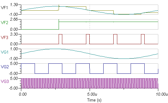
I am now using ADS7064 in TINA, but I got some questions about the pins of this compact model:

1, What are the pins sampled AINP_sampled and AINM_Sampled used for? Are they used for showing the output wave of this ADC?

2, Where could I got the output wave of this ADC?

Thank you!

ADC7046 - autosave 17-12-26 11_28.TSC

  • Hi Haoyang,

    Please find the answer below,

    1) SAMPLE, AINP_SAMPLED and AINM_SAMPLED are additional output (dummy) pins added to the TINA model for tapping internal signals. These pins are not present in the actual device

    SAMPLE: Digital signal.

    Output 1 - Means Device is in acquisition mode,

    Output 0 - Means Device is in conversion mode

    AINP_SAMPLED: AINP pin's voltage sampled on internal sampling capacitor is tapped using AINP_SAMPLED pin.

    AINM_SAMPLED: AINM pin's voltage sampled on internal sampling capacitor is tapped using AINM_SAMPLED pin.


    This ADC model primarily includes pin leakage currents and ADC SHA (Sample & Hold) circuit.

    Output of this SHA is available on the AINP_SAMPLED & AINM_SAMPLED Pins

    2) Digital Output Bits will not be available from this ADS7046 model, as this doesn’t really have A-to-D converter.

    Output for this model are,

    1. Sample & Hold Ckt outputs (the AINP_SAMPLED & AINM_SAMPLED)

    2. Sample signal which indicates ADC mode to the user(equivalent to busybar)

    Please find attached a simple TINA test-bench of this model which will capture the pin functionalities.

    E2E_ADC7046.TSC

    See snapshot of the output of the attached Test-bench below,


    Regards,

    Ahana

  • ADC7046.TSCHi Ahana,

    Thank you for your help, but I got some strange output waveform in my model which is different form the one in you diagram. Could you please tell me what caused this problem.

    Best regards,

    Haoyang

  • I mean why there are some spikes at the beginning of each output waveform.
  • Hi Haoyang,

    Did you mean the spike (highlighted in below snap) at the input waveform,

    This is due to the 1n cap of the TB, connecting suddenly to the sampling cap in acq phase.

    This will be eliminated by use of buffers as shown below,

    The output waveform simulation only significant shows a spike at the first acquisition, this can be due to internal implementation. There may be additional switching activity on the sampling cap, connecting it to some other voltage, which can cause this.

    One need to look into the model architecture & see the implementation, to understand the cause of the initial spike, however this is an encrypted macro.

    After the first acq, no significant spike is seen though, the small perturbations indicate the cap settling time. Test bench is attached herewith.

    ADC7046_1.TSC


  • Hi Ahana,

    Thank you very much for your help! It's perfectly solved my questions. By the way, would you mind explain to me what is "cap of the TB" and how do you know the cap is 1n?

    Best regards,
    Haoyang