This thread has been locked.

If you have a related question, please click the "Ask a related question" button in the top right corner. The newly created question will be automatically linked to this question.

TINA/Spice/OPA189: Stability beat frequency in current monitor/controller

Part Number: OPA189
Other Parts Discussed in Thread: TINA-TI,

Tool/software: TINA-TI or Spice Models

I am trying to use OP189 amplifiers to monitor and control currents.  I attached the simulation file.

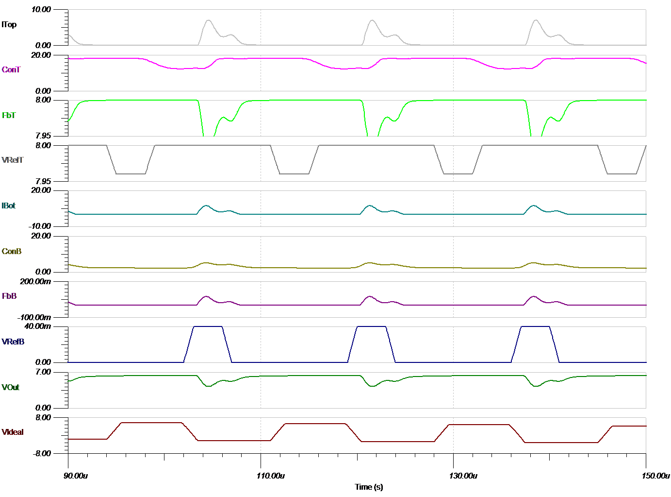
The circuit is unstable at a low frequency.  If you run the simulation, you can see it performs as expected for a few cycles about 444us after the start.  Then it goes astray and returns later for another few cycles.  

There is a second ideal test circuit in the design to demonstrate the ideal output waveform.  The test circuit using an ideal supply and ideal capacitor also seems to wonder so something I do not understand is affecting the circuit simulation.

Looking at the inputs and output of the OPA189 it seems to quit trying to control properly.  I suspect something is just wrong with my simulation setup.

I think the circuit can work because I see it perform as expected, briefly.  I have not found any way to make it more stable.

I am open to any ideas to modify the simulation, tweak this circuit, swap parts, or redesign completely to meet the goals described in the schematic.

rampTop.TSC

  • Hi Barry,

    Not sure if you have tried playing with the output stage. I changed it to FETs and at least the instability went away. However I am not sure if that is the output you are looking for. I would recommend playing with the output stage some more to fine tune the design.

    rampTop_NG.TSC

  • Thank you so much for looking at my circuit.  I really appreciate the help.

    I would much rather use FETs.  The current measurement is more accurate without the BJT base current.  When I tried using fast enough FETs, their capacitance was too high for the OPA189 and it went into high frequency oscillation.  I think the FET you chose is slow enough it filters that effect.

    Your solution is stable, but still not functional.  I attached a bit of the trace.  You can see the VRefTop changes, and causes a difference from VFeedBackTop, but the output of the OPA189 stays railed near 18V.    It sure seems like a simulation issue.  I can't imagine the part will actually behave that way.

    Do you have any other ideas?

  • Hi Barry,

    There may be a delay due to FET parasitics. You can see that after VrefT changes at ~ 94us, the ConT does start to fall below 18V after some time (around 96us).