This thread has been locked.

If you have a related question, please click the "Ask a related question" button in the top right corner. The newly created question will be automatically linked to this question.

TINA/Spice: Check stability in a circuit

Other Parts Discussed in Thread: TINA-TI

Tool/software: TINA-TI or Spice Models

hello, 

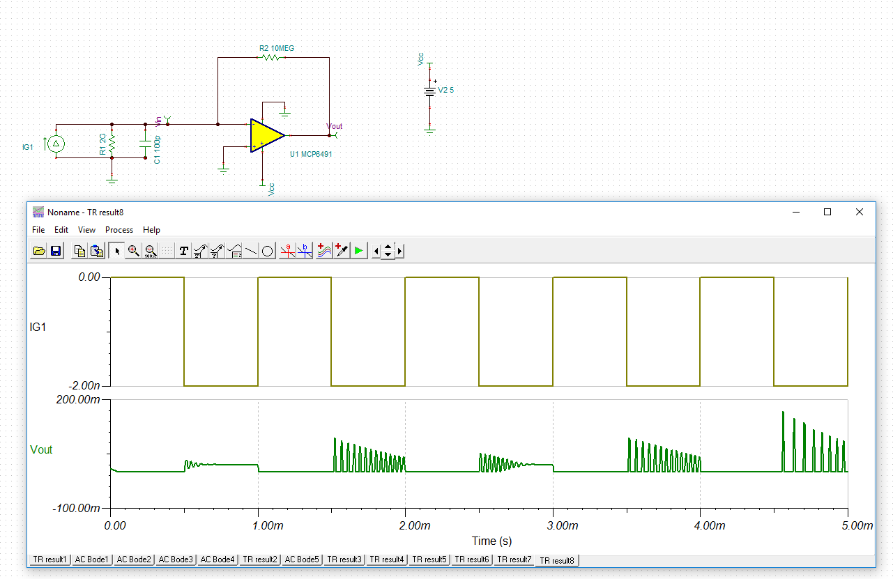
I'm trying to design a transimpedence amplifier to simulate a pulse sensor for heart beat using a photodiode. I generate a square wave ( to simulate the pulses) but I can't see the instability of the circuit in output. This circuit is instable, because there isn't a capacitor feedback  to introduce the zero in the bode plot. If I do the bode plot I can see the peak in frequency, but I can't see the instability in the transient analysis(time domain).

Please help me

Thanks

OPAMP_BODE_MCP6491_forum.TSC

  • Hi Emidio,

    You are correct, the circuit is unstable.But you are not seeing oscillations / instability in the transient simulations as the simulator is taking very long time steps due to the input square wave frequency of 2s and total simulation time of 10s. Due to very long time-step compared to the circuit bandwidth the simulation is not accurate.

    I reduced the total simulation time to 5m seconds and input square wave frequency of 1kHz and you can clearly see the instability in transient analysis.

    Please use feedback capacitor to improve stability (5pF feedback cap may be sufficient in your case). You can go through the following app note to learn more about compensating Transimpedance Amplifiers -  http://www.ti.com/lit/an/sboa055a/sboa055a.pdf .

    Regards,

    Srikanth Pam

    Online Design Tools

  • Thanks. I have a question. Is the input capacitance of the OPAMP included in the model ? Or I have to put it in my scheme?

    Thanks for the help