This thread has been locked.

If you have a related question, please click the "Ask a related question" button in the top right corner. The newly created question will be automatically linked to this question.

SwitcherPro Online-Version TPS40055

Other Parts Discussed in Thread: TPS40055

Hi TI,


in the TPS40055 there must be several errors:

Look at the BOOST-Pin, that is connected over an resistor direkt to the SW-node. (In the Desktop Version it is correct connected over an capacitor)

Look at the SW-Pin that is connected over an capacitor. (In the Desktop Version it is correct)

The Feedback network has different resistor and capacitor names as in the desktop version. Additionally I think that they are displayed in the

wrong place. I know that because I tested the desktop version, in which I get a good phase margin. When I try that in the online version I get a negative phase margin. Ok I am not sure what is wrong there because it is very crazy.


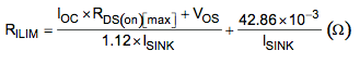
Last: Are you sure the resistor on the ILIM-Pin is calculated correctly? For 2.82A I calculate myself 7.75kOhms. But the SwitcherPro gets 1.78kOhms. What is right?

Thanks a lot. (The Desktop Version works in a way I like)

Greets

Bernd

  • Hi Bernd,

    Your observation about the schematic in the online version of SwitcherPro is correct. As is shown in the datasheet, the BOOST pin should be connected to the switching node through a capacitor. The SW pin should be either connected directly or through a resistor to the switching node. It turns out this this problem also exists in the latest version (v3.8.34.25907) of SwitcherPro for the desktop. If your SwitcherPro Desktop is showing you a schematic that is correct, then you are running an older version of SwitcherPro, maybe v3.8. :-)

    This schematic was redrawn (incorrectly) between release v3.8 and v3.9. Please see schematics for comparison below.


    Correct schematic in v3.8:


    In version v3.9, capacitor C3 is drawn in the wrong place:


    The development team was made aware of this issue today by another customer. We are working on fixing this problem. We are very sorry about any inconvenience or schedule days this issue may have caused you.

    Your second question was regarding resistor R6, which is connected to the ILIM (current limit) pin. Looking at equation 15 for R_ILIM on page 15 of the datasheet, you will notice that R_ILIM is a function of R_DS_on of the high-side FET.

    The default result produced by SwitcherPro will use a TI NexFET Power MOSFET (CSD16xxx). These devices have very low R_DS_on compared to some other devices in the marketplace. As a result, the R_ILIM will be low, typically around 1k ohm. If you substitute in a lower-end high-side FET, with much greater R_DS_on, SwitcherPro will re-calculate R_ILIM. I have seen values as high as 50k ohm. So, are you using the same high-side FET in your hand calculations as you are selecting in SwitcherPro? And, if yes, what R_DS_on value are you using in your hand calculations, vs. the value in the device table list in SwitcherPro?

    Thank you for evaluation TI parts in SwitcherPro.

    Regards,
    Michael

    Michael Krasnicki
    Analog eLab
    Texas Instruments

  • Hi Michael,


    thanks for your reply.

    You didn't notice the Feedback Loop errors, but I think you recognized them too.


    About the current limit: I now checked the max. R_DS(on) resistor in my MOSFETS. I have Infineon type with a R_DS(on) of 16.25mOhms. I took them into SwitcherPro with
    45mOhms @ 2.5V, 30mOhms @ 4.5V and 10mOhms @ 10V.

    And for myself I calculate with 16.25mOhms:

    R_ilim =( (2.82A * 16.25mOhms - 20mA) / ( 1.12 * 8.5uA) )+ ( 42.68m / 8.5uA  ) = 7.75kOhms

    And SwitcherPro calculates with my MOSFET and a max current of 2.274A a R_ilim = 1.33kOhms.
    Perhaps you can clarify that as well.

    Thank you


    Regards,

    Bernd

  • Hi Bernd,

    Further investigation has revealed that the equations used to calculate R_ilim in SwitcherPro are significantly different then the equations in the data sheet. I am following up on these discrepancies.  For now, please use the values obtained from the data sheet equations.

    And, yes, you are correct. There are several other differences between the v3.8 and v3.9 schematics. These will need to be fixed too.

    We regret any problems or delays these issues may have caused in your project.

    Regards,
    Michael

    Michael Krasnicki
    Analog eLab
    Texas Instruments