


Other Parts Discussed in Thread: ENERGIA, UCC27321, SN74LVC2G14
Hello all,
I've recently started working on implementing TIDA-00663 LiDAR reference design and I came across some obstacles, enumerated next:
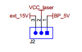
1) What is the function of ext_15V? I don't see any connection to this pin.
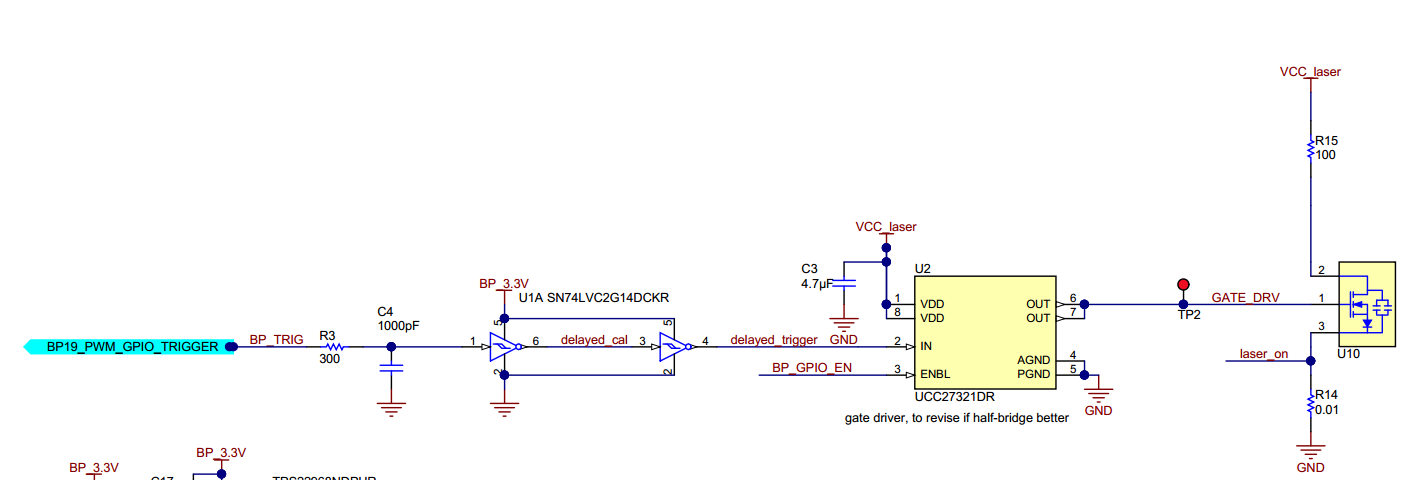
2) About the laser driver (UCC27321D) I had a huge problem. First, I only soldered the TX part of the circuit (image below) and when I connected it to an external Vcc_laser = 10V (power source), while keeping ENBL floating (internally pulled-up), it basically overheated and released a white smoke. I can assume it burnt. I already verified and all the pins are correctly connected. Furthermore, when using the MSP430F5529LP connected to the TIDA-00663, and if I connect Vcc_laser for e.g. to the board +5V pin, the board automatically disconnects from the PC. Can someone please help me understand what is going wrong? Is there something that I'm missing or doing incorrectly?
3) Is there any C++ or C code for triggering the Laser using nanosecond pulses? I used Energia but digitalWrite() is too slow and introduces delays of about 1-2us and the solution I found is to program at a lower-level. This is my code:
#define ARDUINO_MAIN
#include "wiring_private.h"
#include "pins_energia.h"
#define nop __asm__ __volatile__("nop\n\t"); //define a nop (no operation) instruction to waste only 1 clock cycle (1/25MHz = 40ns)
#define BP_TRIG P2_0 //Laser Trigger signal
#define BP_GPIO_EN P7_4 //UCC27321 (MOSFET driver) enable
#define STOP P2_1
//When this button is pressed, the Trigger signal stops by entering a infinite loop; To quit the loop, the RST (S3) button must be pressed, which restarts the Triggering Signal
#define LED P1_0 //turned-on when trigger is stopped
unsigned int T_pulse = 100; //T_pulse=1/PRR must guarantee that duty_cycle < 0.1% (Laser limit)
void my_digitalWrite(uint8_t pin, uint8_t val) //pre-defined function introduces too much delay
{
uint8_t bit = digitalPinToBitMask(pin);
volatile uint8_t *out = portOutputRegister(digitalPinToPort(pin));
(val == LOW ? *out &= ~bit : *out |= bit); // substitutes if statement - see if faster
}
void setup(){
pinMode(BP_TRIG,OUTPUT); //define both pins as outputs
pinMode(BP_GPIO_EN,OUTPUT);
pinMode(STOP, INPUT_PULLUP); //Activate STOP button
pinMode(LED,OUTPUT);
digitalWrite(BP_GPIO_EN,HIGH); //Enable Driver
my_digitalWrite(BP_TRIG,LOW); //Laser Off
attachInterrupt(STOP,trigg_stop, FALLING); // Interrupt is fired when button is pressed
my_digitalWrite(LED,LOW); //Enable Driver
}
void loop(){
delayMicroseconds(T_pulse); //OFF period in microseconds
my_digitalWrite(BP_TRIG,HIGH) ;
nop; //each nop introduces a ~40ns delay @ 25MHz
my_digitalWrite(BP_TRIG,LOW) ;/
}
void trigg_stop()
{
my_digitalWrite(BP_GPIO_EN,LOW); //Enable Driver
my_digitalWrite(BP_TRIG,LOW); //Laser OFF
my_digitalWrite(LED,HIGH);
while(true){} //infinite cycle until RST (S3) button is pressed
}
4) Is there any SPICE model for Schmitt-trigger SN74LVC2G14 or similar? Or is there any other way of simulating it ?
Thanks in advance,
Joaquim

