Other Parts Discussed in Thread: TINA-TI,
Tool/software: TINA-TI or Spice Models
Hi everybody,
I'm new to this forum, so please feel free to correct me if I'm making mistakes.
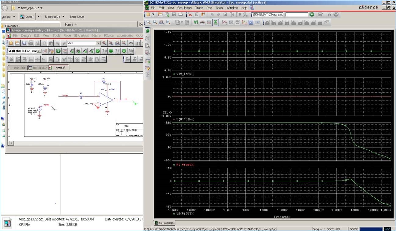
As the title suggests, I'm currently trying to simulate a design containing the OPA322. I downloaded the model from TI website and followed all the instructions contained in Application Report SLOA070 ("Using Texas Instruments Spice Models in PSpice"). I found that the when running an AC sweep simulation, the results are not correct. To better explain what I'm telling you, I implemented a very simple design, that I attached, which is a basic circuit with an OPAMP in non-inverting configuration (schematic.jpg).
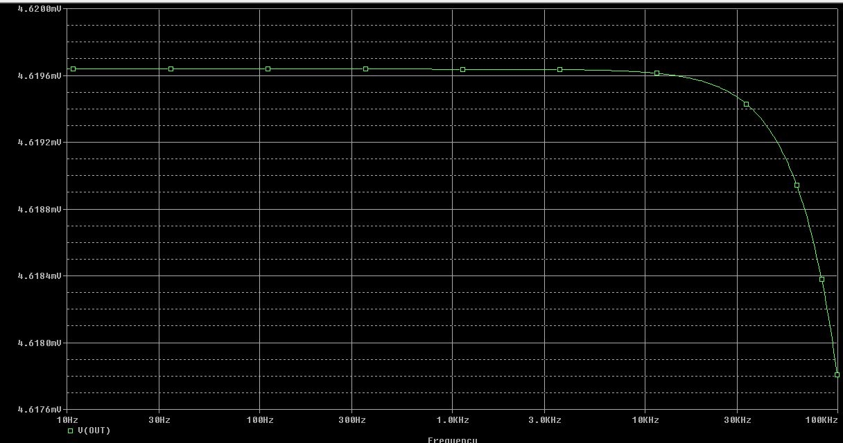
If a run a transient simulation, using a sinusoidal waveform as the input (0.5V amplitude, 200Hz frequency), the output voltage is what I expect (transient.jpg). If i run an AC_sweep simulation, the results does not make any sense (ac_sweep.jpg) (I would expect an output of 0.5V in all the pass-band). Looking at the transient simulation I've seen that there is a small glitch at startup (transient_detail.jpg), but I do not know if this has something to do with the weird result.
I've also tried to use TINA simulator, but with that tool everything worked fine. The only problem is that I have to use Cadence OrCad, so I need the model to work with this simulator.
Thank you in advance
Pietro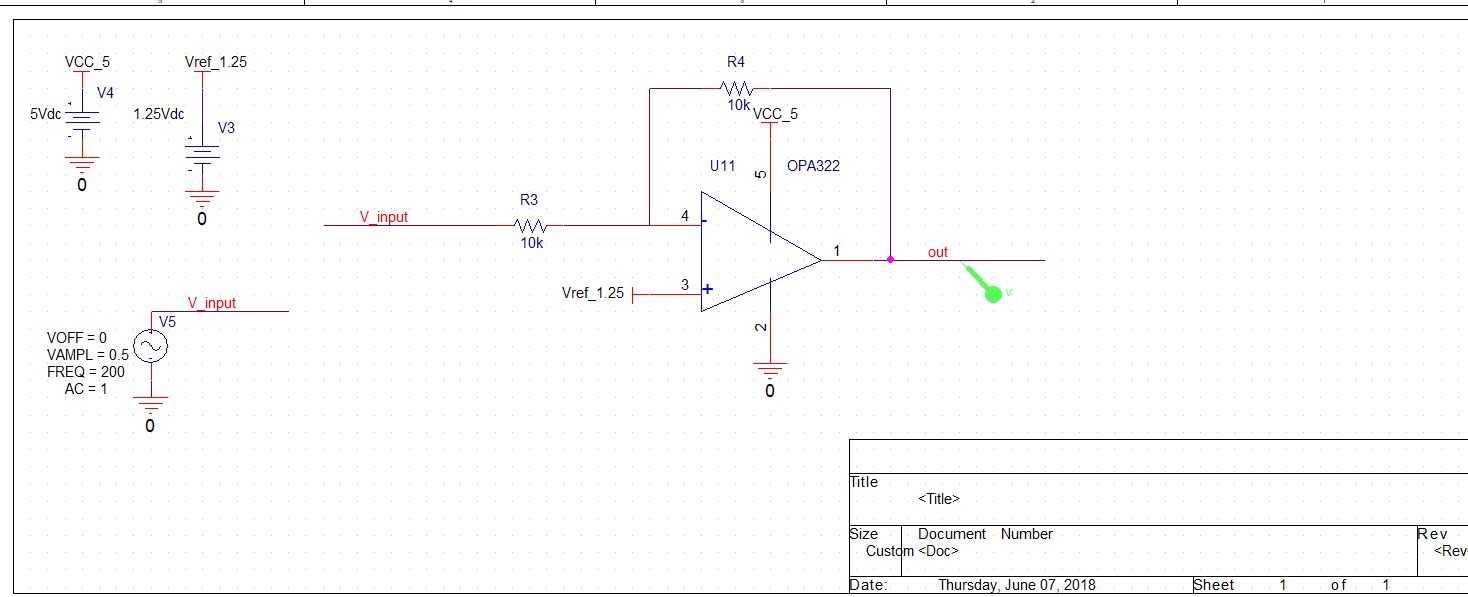
![]()
![]()
 test_opa322.zip