Part Number: TIDA-00951
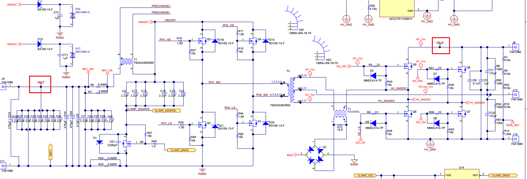
The Vds of Q9/Q8/Q7/Q6 is twice VBUS.And the output voltage of VBAT keep constant when I change the duty of Q6~Q9 from 3% to 35%.
Recently,I use the TIDA-00951 reference design to develop a product.But some problems happened when I tested its charging function.
In the high-voltage side VBUS power supply 24VDC, low-voltage side 200 ohm resistor as a load.The driver of Q6 is same as Q8.The driver of Q7 is same as Q9.The duty of Q6 is same as Q7 but phase shift 180°.
For watching the current of transform coil Pin12/13 to Pin 18/19,I cut the 12/13 pin of transformer T2 to the Q7/Q8 connection and connect a 100 ohm resistor RL in series.Then I catch the voltage of RL.
And there were no driver on the Q1~Q5.
Q1.The output voltage of VBAT keep constant when I change the duty of Q6~Q9 from 3% to 35%.Why?
Q2.Q9 drain-source voltage appears twice as high as VBUS voltage spike when the Q6 & Q8 turn-on instead of Q9 turn-off.Why?
Q3.The driver of Q6~Q9 is perfect when there is no power on the VBUS.But the driver ringing appears when I apply power at the VBUS.Why?
Note:The voltage of VBUS is 24VDC.