This thread has been locked.

If you have a related question, please click the "Ask a related question" button in the top right corner. The newly created question will be automatically linked to this question.

CCS/TIDA-01212: TIDA-01212: problem of sce of tida 1212 IR RX part

Part Number: TIDA-01212
Other Parts Discussed in Thread: CC1310,

Tool/software: Code Composer Studio

Dear sir,

I have two cc1310 launchpad ,and i am working on the tida-1212.

and i want to test the irda part with irled.

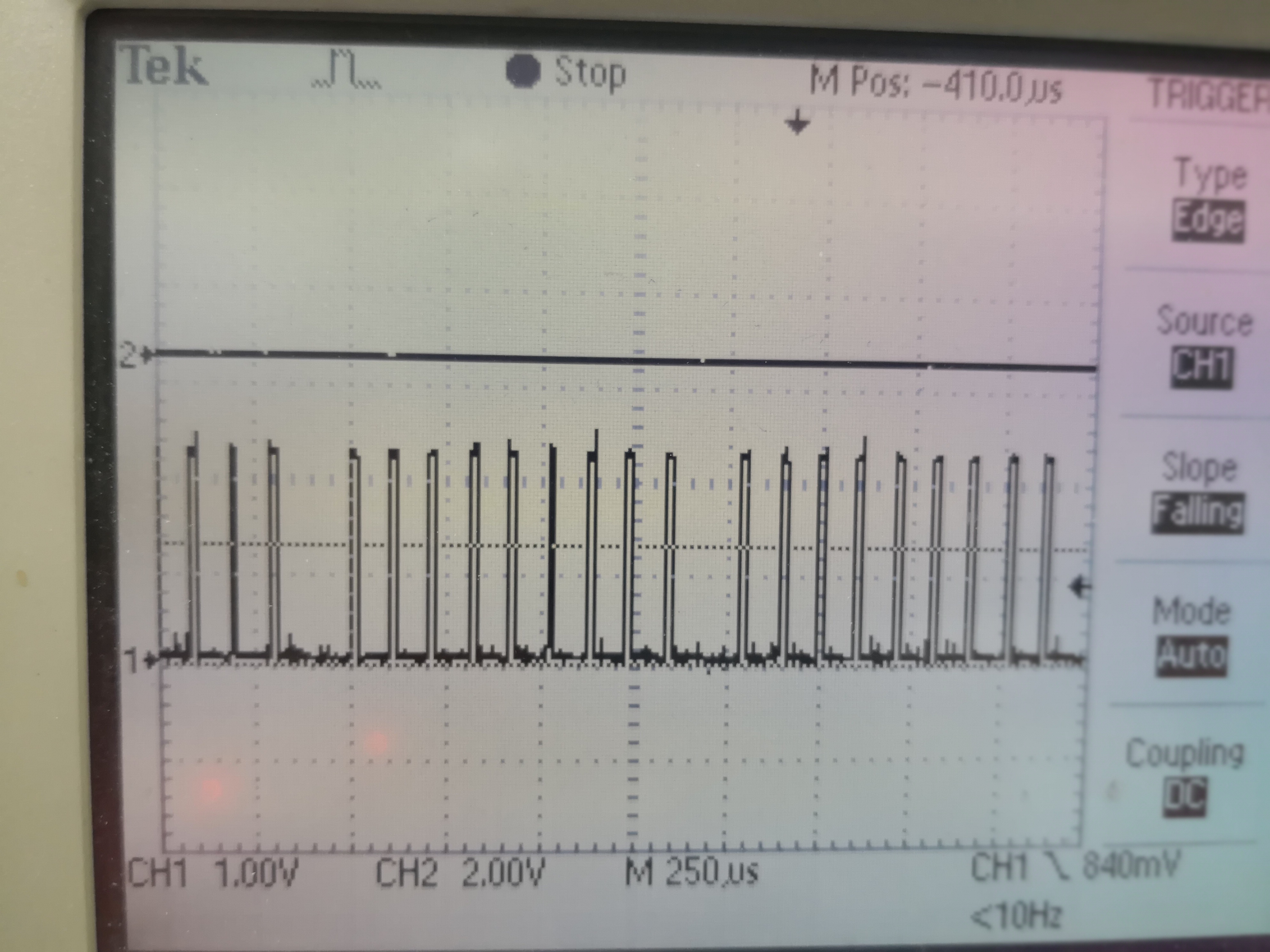
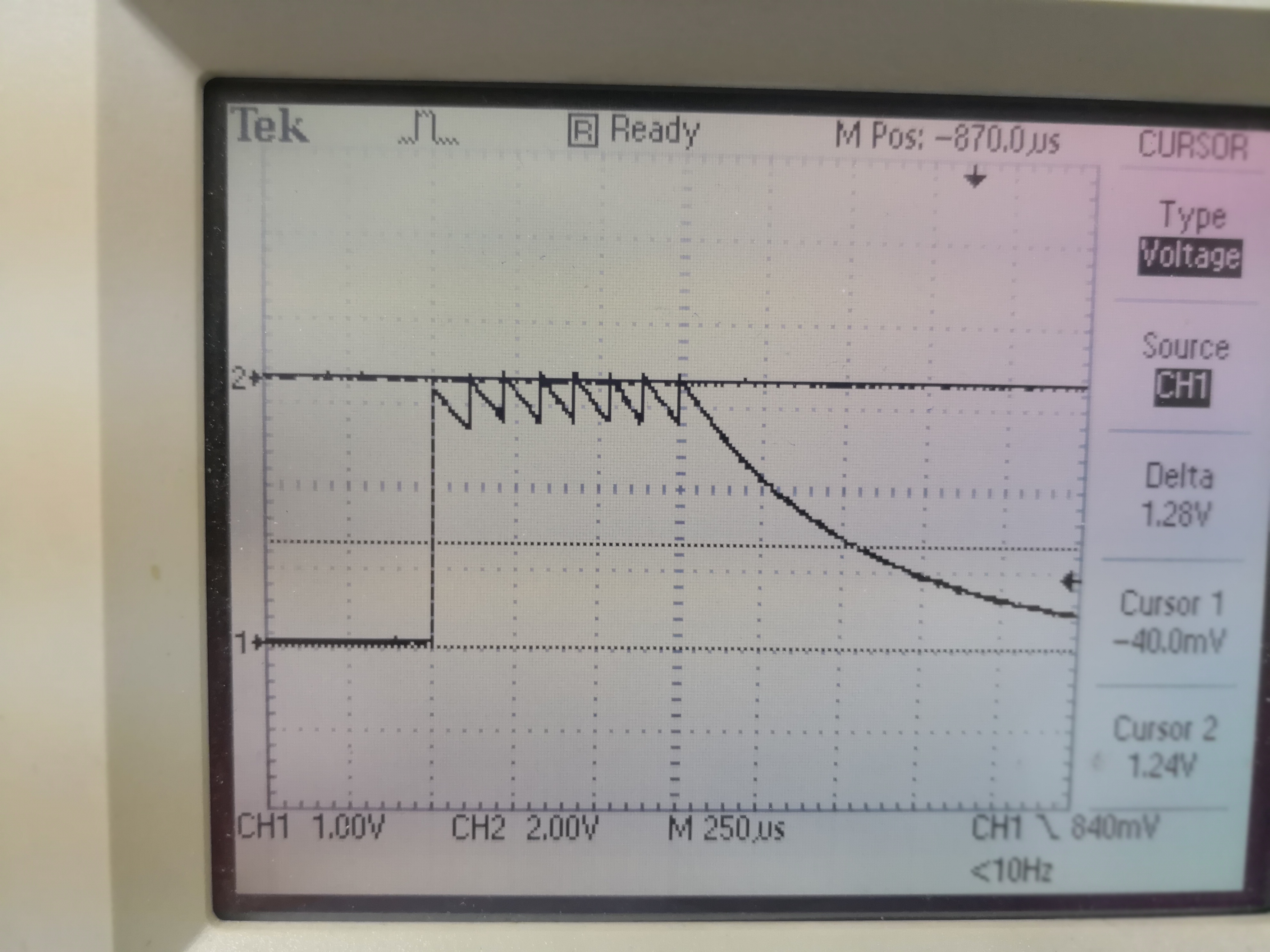
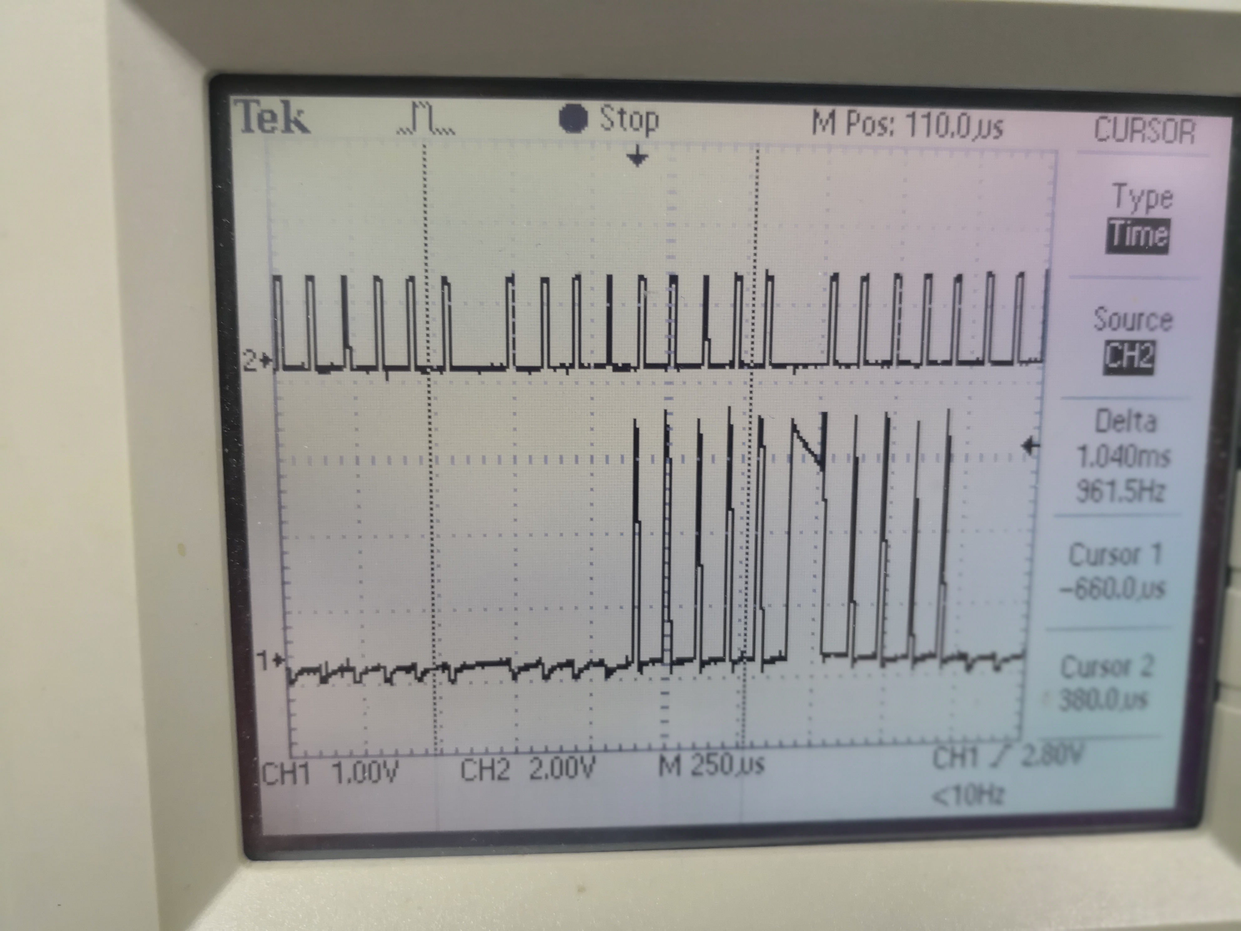
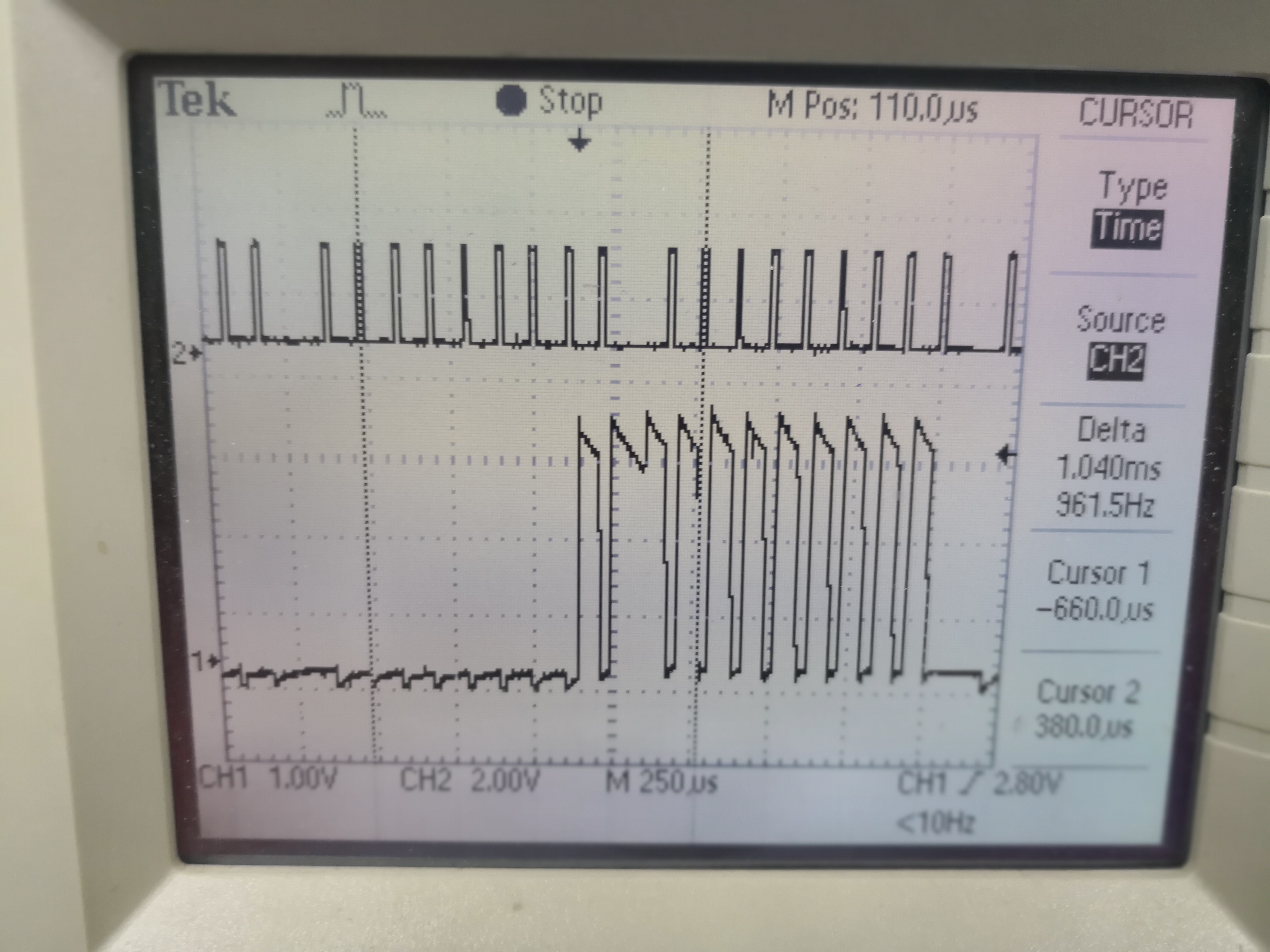
I have test the TX is working according to here:

now i want to test the RX part, o have several question to ask :

1) it seems that i cannot open two sensor controller studio in 1 pc, right?

2) If yes, can i made one working in offline mode?

3) Any tutorial that i can port the code into ccs? for the tutoral in scs, it only show the generated code and then no detail of working in  ccs.

thanks

Jeff

  • Jeff,

    let me try to answer your questions:

    1. right, only one Sensor Controller Studio instance per PC.
    2. Not sure what you mean here. You could actually create a CCS project, that does periodic TX using the Sensor Controller and flash it onto the CC1310. After restart of CC1310 you do not need the Sensor Studio, the CC1310 should be transmitting as per your CCS project. For this you will need to create a project as described in item 3 below.
    3. A Tutorial is found under the SimpleLink Academy here:  dev.ti.com/.../

    i have added a link screenshot as well.

    Using CCS Studio you can import the CCS project which works in combination with the Sensor Controller examples, such as the ADC_window_monitor:

    C:\Program Files (x86)\Texas Instruments\Sensor Controller Studio\examples\adc_window_monitor_launchpad

    Regards,

    Milen

  • HI milen,

    i have an updated question regarding with the irda part of the TIDA-01212.

    So far i have two cc1310 launchpad and so one will be doing ONLY TX and one will be doing ONLY RX for testing purpose at this moment.

    In the TX code ,

    i have some question regarding:

    i have deleted the RX part and make input.enable = 1,

    regarding the tx code:

    1)for(U16 n=0;n<16;n++) , seem it will send a 16bit data. I can observe a 16 bit waveform around 2.1ms

    i would like to ask if the tx packet is 1 start bit and then 7 bit content and 1 stop bit ?

    2) For the RX part, i have never get my waveform below 1.27V

    According to datasheet, it Says "The exact voltage reduction depends on the intensity of IR light as well as the relative timing

    of the bit pulse versus the polling bit time slot"

    I didnt use TSPF6200 as suggested.

    attached are waveform of TX and RX

    thanks

    Jeff

  • HI ,

    I gone through the application note the data pattern is 10-bit format/

    But i still didnt receive anything in the rx side,

    Thanks

    Jeff

  • Jeff,

    it is impossible for me to help you debug all your problems when you are using different LED, I have no idea how sensitive it is.
    Have you put the LED directly next to each other to ensure max. IR light coupling into the receiver?

    if the LED is around 900nm, you can just use a Remote from a TV or SAT receiver (i used a cheap universal remote) and use that as TX to verify your RX part; at least you should be able to see drop below 1.27V.

    Note that the challenge is to have TX and RX at the same time.
    So use a continuous TX, eg a few seconds with no breaks to ensure TX sequence is long enough to hit your RX window.

    Regards,
    Milen
  • HI  milen,

    thank s again for your reply.

    I now change the IR LED to the reference one and now the hardware works.

    Note that the challenge is to have TX and RX at the same time.

    That what i encounter now, as the program provide is a while loop programme,

    what i can adjust in order to have TX window much larger than the RX window,

    for the TX (or actually the RX part), what i can do is to adjust the value "K" so i try to modify the value of K to be higher say "50"  so that the TX window is much higher than the RX, and i have set the adress to be '0"

    and the problem is as below:

    and the SCS result

    it seems that the "false detection" of the start bit will cause the error,

    so how to solve it?

    And i do not understand how the value of K to be assign in RX part,

    for provided RX . k = 7 , and so only 6 bit will receive...............

    thanks if you can point out  my problem ~

    thanks

    Jeff

  • Jeff,

    are you using CC1310LP to transmit under SCS?
    I mention in the UG that you need to enable the Higher Driver strength (available only on a few pins of CC1310) to get 8mA, see Chapter 3.5

    Higher TX current will help you get larger voltage drop on the RX side.
    Same effect you can achieve if you put the TX LED and the RX LED closer together.

    If both of the above don't help (=the voltage does NOT drop below 1.27V on the RX side), then your next option is to use an external Voltage divider which creates a Reference voltage above 1.27V DCOUPL. See Ch. 2.5 of UG: "if an external resistor divider is used (allowing to extend the IR link range), then the REF and the IO1 lines are necessary."

    K=7 was used to detect a wake-up signal of "0x0F" and is really optimized for Ultra low-power.
    The implementation of a protocol over the IrDA PHY layer is outside the scope of this TID.

    So after detecting the wake-up, you will have to take care of the data bytes you want to transmit, the message formatting, the timings between TX and RX and so on.

    Regards,
    Milen