


Other Parts Discussed in Thread: MSP430FR5969, OPA857
Hi,
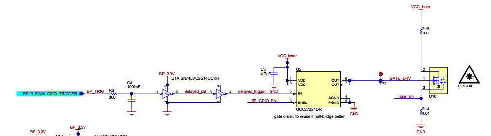
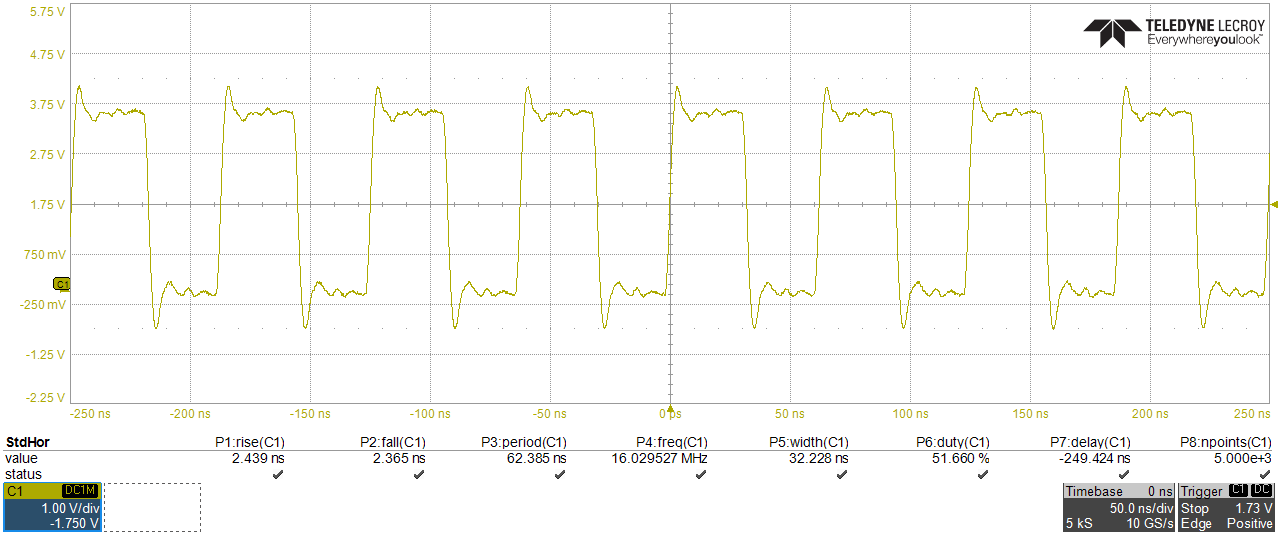
In the TIDA-00663 reference design, I've been using a 16MHz external CLOCK source from an MSP430FR5969 to the TDC7200.
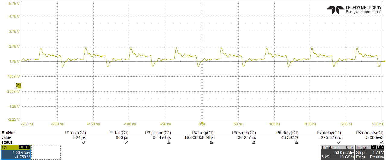
However, I've just noticed that at the OPA857 output, there is an oscillation with the same 16MHz frequency.
The PCB has every component soldered except the laser driver (U2) and the Laser (U10), as the respective resistors and capacitors

The code I've used to setup the OPA857 and the TDC_CLK is the following:
#include <msp430fr5969.h> #include <SPI.h> #define nop __asm__ __volatile__("nop\n\t"); // no operation instruction that wastes 1 CLK cycle (1/16MHz=62.5ns) void setup() { // Setup the system // WDTCTL = WDTPW | WDTHOLD; // Stop the Watchdog Timer => AFFECTS Serial communication PM5CTL0 &= ~LOCKLPM5; // Disable the GPIO power-on default impedance mode to activate previously configured port settings // Output SMCLK in P3.4 (dedicated pin) with the same frequency as F_CPU=16MHz (maximum for TDCs) - TDC_CLK P3DIR |= 0x10; // Set P3.4 as an output P3SEL1 |= 0x10; // Select SMCLK function (Table 6-57 from MSP430FR5969 datasheet) //Set the OPA P3DIR |= 0b01100000; // Set OPA857 (TIA) gain in CTRL pin P3.5 (5k_gain_setting_BP9_P3.5) and Test_mode in P3.6 P3OUT &= ~0x20; // If TIA_gain = 5 => P3.5 = '0', if TIA_gain = 20 => P3.5 = '1' P3OUT &=~ 0x40; // Disable test mode in P3.6 (tprop_calibration_enable_BP10_P3.6 <=> Test_SD writen to '0') } void loop(){ // Code to run repeatedly nop; // Nothing happens here, when TDC finishes, an interrupt is activated nop; } |
As a result, I get the following signals as, respectively, Clock and OPA outputs. One should note that if I increase the OPA gain to 20kOhm, naturally the output oscillations are also amplified.
If someone could help in finding the source I'd gladly appreciate it.
Thanks in advance,
Joaquim
