


Other Parts Discussed in Thread: TINA-TI,
Tool/software: TINA-TI or Spice Models
For the past 2 days I have been trying to simulate a simple 5v 3A buck converter making use of the LM2678-ADJ. I followed the datasheet application note using the design equations to come up with a design. I downloaded the LM2678 spice model from the TI website and imported into LTSpice XVII. Unfortunately the design did not work as expected, I detailed the results in this stack exchange post. I eventually discovered that the spice model available on TIs site is for the fixed 3.3v version and not the adjustable version. After trying to change the internal resistance values in the spice model and obtaining the same result I decided to instead try the TI web-bench power designer to simulate the design. Entering my desired parameters produced nearly the same component choices as the ones I had obtained using the design equations by hand. However the simulation results shown below for steady-state and load transient do not make any sense. Another user on stack exchange tried the same circuit and obtained the same results at which point it was suggested there may be a bug in the spice model and that I should try get support on here.
The simulation results are shown below for a 5v 3A buck converter using the LM2678.
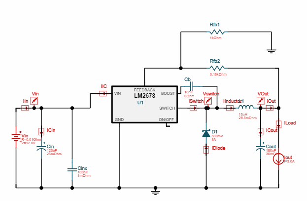


Could someone please assist me in getting a working simulation of the circuit design shown above or at least explain to me why this circuit configuration is not viable?
