This thread has been locked.

If you have a related question, please click the "Ask a related question" button in the top right corner. The newly created question will be automatically linked to this question.

WEBENCH® Tools: WEBENCH : ISOLATED TRANSFORMER CONNECTION


Tool/software: WEBENCH® Design Tools

i design an isolated power supply using WEBENCH, in that there is a transformer at the output of the switcher IC.

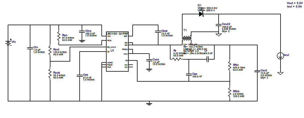
The transformer connection in the workbench schematics is given below,

But the when i look into the datasheet of transformer i got like this,

Now, i am in a trouble... how i connect the transformer. In the BOM given transformer has 12 pins buts in the schematics it was only four(2 input and 2 output pins).

please explain the connection?

Transformer details,

Wurth Elektronik

Part No. : 749196521

Lp= 48.0 μH
Rp= 142.2 mOhm
Leakage_L= 480.0 nH
Ns1toNp= 2.0
Rs1= 284.4 mOhms

Full Schematics given below,

  • Hi Arun,

    The connection pins of the transformer is used to configure the primary inductance of the transformer. For example, if 12 and 2 are connected then the total inductance is Lprim*2^2. Since Lprim = 12uH for 749196521 ,the total inductance calculated is 12*4=48uH.Please use the appropriate pins of the transformer based on your application. The remaining pins of the transformer can be floated.

    Thanks & Regards,
    Praveen B
  • Did you mean that, for primary side connection short 12 and 2 pins?

    Transformer design details as per webench is given as,

    Lp= 48.0 μH
    Rp= 142.2 mOhm
    Leakage_L= 480.0 nH
    Ns1toNp= 2.0
    Rs1= 284.4 mOhms

    Could you please elaborate the design.

    Also it is given as "Ns1toNp= 2.0"

    I would be thankful if you can explain input and output connections w.r.t. the designand transformer

  • Hi Arun,

    We know that for an inductance winding, L is directly proportional to N squared. So when you connect 2 windings in series on N turms the effective inductance becomes directly proportional to the 2N whole square which is 4*N*N. Hence the L turns out to be ~48uH

    The turns ratio calculation:

    As you can see FB node is at Vref. So Vo1 will be at Vref*(Rfbt+Rfbb)/rfbb

    Now you know Vo1 and Vout. Turns ratio will be Vout/Vo1 ideally. In the actual equation, we take care of diode drops as well.

    Hope this is clear.

    Thanks and Regards,

    Praveen B

  • Dear Praveen,

    Thanks for the detailed explanation,

    few more help needed,

    As per you reply i understood that at the primary side i need to connect two winding's in serial(to achieve primary L = 48uH approx).

    also in this design it is stated that "Ns1 to Np is 2.0", so please explain how i connect the secondary side winding's.

    Do i need to connect all other windings(4 number) in serial to achieve Ns to Np ratio to 2?

    I will be thank full if you explain the full connection, because i'm a litlle confused about the transformer connection.

  • Hi Arun,

    Please note that in order to achieve turns ratio "Ns1 to Np as 2.0" you need to connect four secondary winding in series.

    In this case you need to connect 9 to 5, 8 to 6 ,7 to 3  and the output is measured between 4 and 10.

    Let us know if you have any further questions. Also please share the input/output conditions for the future queries.

    Thanks and Regards,

    Atul