This thread has been locked.

If you have a related question, please click the "Ask a related question" button in the top right corner. The newly created question will be automatically linked to this question.

TINA/Spice/TINA-TI: How to change 'Probe' reference point.

Part Number: TINA-TI

Tool/software: TINA-TI or Spice Models

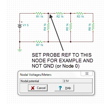
When using the 'probe' tool following a simulation, how does one chance the reference point?  It appears that the node designated as the GND is the only reference.  Is this correct.  If not how is this reference changed?  Seems like a fundamental thing that one would want to do.

Thanks..

Jim

  • Hi Jim,

    Can you clarify what you mean by probe or probe tool? Can you describe what you are doing at TINA-TI such as perhaps you're doing circuit simulation and you click on Analysis -> AC Analysis? And then you go where in TINA-TI?

    If you have some pictures that will help also to see what you're doing and where in TINA-TI.

    Herman
  • Hi Herman -

    What I am trying to explain is that when an analysis has been completed (DC for example below) there are many times where I want to measure a differential signal between two nodes.  I would have thought that the virtual multimeter would work in this capacity.  Two probes would be used and a measurement could be taken between two nodes.  This does not seem to be the case.  I do realize that a VOLTMETER tool can be placed between two nodes but many times it would be nice to simply set the probe reference point (something other than GND) and make differential measurements.

    Is this possible?  If so, I cannot figure out how.

    Please advise.

    Thanks

    Jim

  • I tried to paste an image of a circuit example and could not.  Therefore, I've attached a small image file of what I am attempting to describe.

    Jim

  • Hi Jim,

    Unfortunately, this is not possible. Using Voltmeter is the best way to do this.

    Herman