This thread has been locked.

If you have a related question, please click the "Ask a related question" button in the top right corner. The newly created question will be automatically linked to this question.

PMP20686: UCC28730, UCC28710

Part Number: PMP20686
Other Parts Discussed in Thread: UCC28730

Hi,

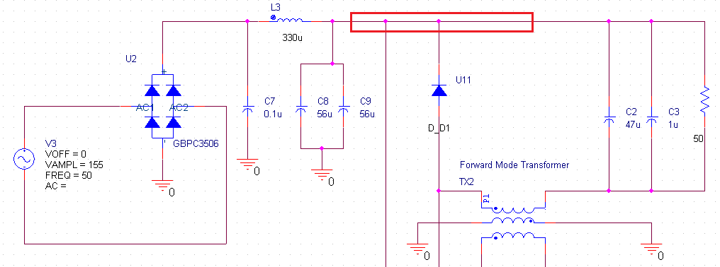
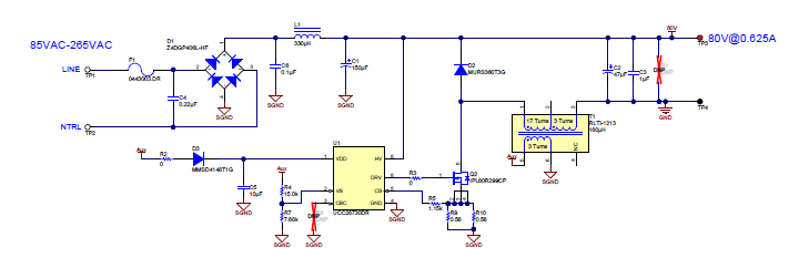
I am trying to simulate the PMP20686 with little modification.

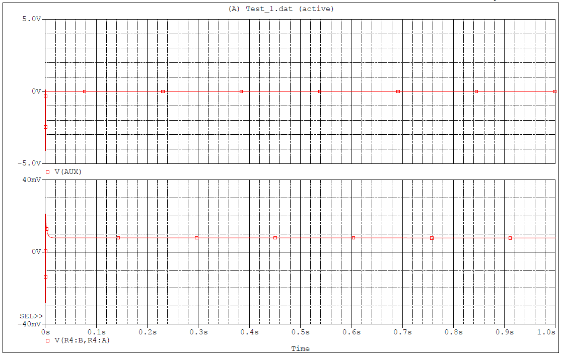
While simulating the IC, we are facing the issue regarding the auxiliary output generation.

Here, the transformer model is same as provided in the Webench UCC28730 transient simulation.

The schematic of the simulation is attached herewith.

Please provide un-encrypted SPICE model for simulation purpose only.

-Rushi

  • Hi Rushi,

    Several questions for you:

    1. What issue are you seeing when simulating UCC28730? Could you please describe in details?

    2. I don't see any attachment on this post, so could you please attached your project?

    3. If you are able to run simulation already, why do you need unencrypted Pspice model for? There is a chance that we might not be able to release the unencrypted Pspice model.

    Herman
  • Herman,

    The simulation results and schematic are attached herewith.

    I want to simulate the same circuit is LTSPICE and for that unencrypted SPICE model is required.

    -Rushi

  • Hi Rushi,

    Could you please attach your project here? This will help us to quickly analyse and resolve the issue.

    Also, we are sorry to let you know that the unencrypted SPICE model is not available for distribution. I apologize for any inconvenience.

    Thanks & Regards,

    Arpan Gupta

  • Hi Rushi,

    I tried to configure the test setup you prepared but unable to replicate the exact issue you are facing. Could you please attach your PSpice project files here?

    Also, it will be very helpful if you can describe the issue in detail.

    Thanks & Regards,
    Arpan Gupta

  • Hi Arpan,

    Please find the attaches zip file of the simulation project.

    UCC28730_PSPICE_TRANS.zip

    In the simulation schematic, Page-1 is available with the UCC28730 TI web page and the second page is modified as per the requirement.

    -Rushi

  • Hi Rushi,

    Sorry for the delay in response. I tried to analyse the circuit designed by you and have the following queries.

    1. I observed the input and output stages are connected together. Could you please explain the reason behind this?

    2. Is the transformer placed properly in your design? Is the AUX voltage generation proper? If yes, What is the expected voltage at AUX node for your design? (Kindly refer the released schematic if you have doubt on how to generate AUX voltage)

    Thanks & Regards,

    Arpan Gupta

  • Hi Arpan,

    For the queries:

    1. In the up-side down buck converter, the switch is placed in return path. Please refer the schematic of PMP20686 reference design.

    2. The transformer is placed properly (Refer PMP20686). In the simulation, AUX voltage is not generated at all (shared results). The expected voltage at AUX is 12 V.

    Please find the attached schematic of PMP20686 80V power supply.

    Thanks and Regards,

    Rushi


  • Hi Rushi,

    Thanks for the clarification. I understand the issue now. Currently we are looking into it. I will update you once we find out something.

    Thanks & Regards,
    Arpan Gupta