This thread has been locked.

If you have a related question, please click the "Ask a related question" button in the top right corner. The newly created question will be automatically linked to this question.

WEBENCH® Tools/TLV62130: How ESR is specified in caps used in Webench

Part Number: TLV62130


Tool/software: WEBENCH® Design Tools

Hi,

Simulating design based on TLV62130 I am not sure how you obtain ESR for the example capacitors you giving for eg:

GRM31CR71E106KA12L webench says ESR=1mohm.

At what frequency you specify this ESR

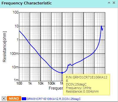
From cap data sheet https://ds.murata.co.jp/simsurfing/mlcc.html?lcid=en-us :

at 100k Hz ESR=8mohm

at 1MHZ ESR=3mohm

Thanks

Sebastian

  • Hi Sebastian,

    We typically use ESR value at 1MHz frequency, if it is specified in the datasheet. Else, we use the lowest value from the impedance chart. In the case of GRM31CR71E106KA12L, it should be 4mohm. We will update the ESR for this cap to 4mohm in the tool.

    Regards,

    Amod

  • Hi, Thanks for thet, I am afraid problem might be wider I checked a few 100nF capacitors you using in webench and theynormally are stating 1mohm ESR while from graphs ( I have checked few vendors ) they normally above 10mohms.

    For example GRM188R61E104KA01D states 1mohm in WB, while from murata data sheet below, it is 20mohms

    Could you please fix this as well

    Sebastian

  • Hi Sebastian,

    Thanks for the additional feedback. Do you have any specific 100nF part numbers that you looked at? We can correct those as well.

    Regards,
    Amod
  • No porblem

    For sure :

    GRM188R61E104KA01D min ESR approx  20mohm

    GRM188R71H104KA93D min ESR approx 5mohm

    C0603C104K5RACTU min ESR approx 104mohm

    UMK212B7104KG-T min ESR approx 8mohm

    One more question from me , how about the dereated capacitance ypu giving in Webench , at what voltage it is calculated?

    Sebastian

  • Thank you Sebastian. Much appreciated. We will have these updated in the next release of the tool which could be around end of March.

    For capacitor derating, we only derated ceramic caps today. And, we do so only for capacitors 1uF and above today. There is a lot of data from manufacturers and we try to get as much in as possible. So, wherever we have this DC bias voltage cap change vs applied voltage curves, we use them to determine the value of the ceramic cap at the applied voltage (as an example, for 3.3Vout, it will use 3.3V value for output cap Cout) But, we have cases where we do not have manufacturer data in for all ceramic caps and in such instances we use linear derating. With the linear derated model, for a 5V output, a 10V rated output cap with nominal value of 44uF will have 22uF value (C_actual = 44uF* (1-5/10) = 22uF)

    Regards,
    Amod
  • Thank you Amod, this resolves my issue and is very helpful.