This thread has been locked.

If you have a related question, please click the "Ask a related question" button in the top right corner. The newly created question will be automatically linked to this question.

WEBENCH® Tools/LM2735: Inconsistent options for alternate parts

Part Number: LM2735

Tool/software: WEBENCH® Design Tools

I'm evaluating a quite old and probably poorly optimised design that uses LM2735Y with input 4.38V-5.25V, output 5.835V at 0.12A. Changing the default WEBENCH design to use our actual components is hampered by some apparently odd restrictions.

A simple but relatively unimportant example is with the feedback resistors, which default to 36.5k and 10k, both in 0201 packages. If I change these to our values of 51.1k and 14k by editing the limits in the Alternate Part Selection dialogue, the alternates offered all have the correct value but only in 0805 packages or larger - why is that? (We actually use 0603 in this case.)

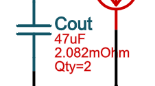
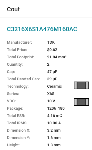
A more frustrating issue is with some of the capacitors. Cin defaults to a 2.2uF X7R ceramic, but the list of alternates (without editing any limits) includes the 10uF X5R part that we actually use (TDK C1608X5R1A106K080AC), so that's fine. On the other hand, Cout defaults to a 47uF tantalum (in spite of the datasheet recommending ceramics!), where our design uses 3 off 10uF X5R, the same part as we use for Cin, but even if I edit the limits I cannot persuade the Alternate Part Selection dialogue to offer this choice. Obviously I can 'create a custom part', and doing it that way suggests that our design is seriously off optimum in this area, with a very low phase margin. However that's an inconvenient method because I have to find out and apply the derating of capacitance value with DC voltage manually, rather than letting WEBENCH do it, which it seems to do very well for standard parts that it knows about. Since WEBENCH allows this part for Cin, why can I not select it for Cout?

  • Hi Richard,

    For any alternate passive component, it is possible we do not have all the components in our database with all package sizes. In addition, some components have additional constraints as compared to others like package size, technology type, etc. that may cause the alternate part lists to not be the same from one component to the other (Cin to Cout)

    If you can please share your design URL using the screenshot below as reference, then we can find out more on this. I am assuming since it is an old design, that is comes from Flash version of the tool.

    If it is in the HTML version of the tool, please see screenshot below for reference:

    Regards,

    Amod

  • Amod,

    Thanks for your reply. To be honest, for you to be able to replicate the issues outlined in my first post above you really need to start with the default WEBENCH design for my input and output requirements (before I've started customising it to use our actual component values). The following is a therefore a link to a new default design that I've just created (#42 in My Designs) using the HTML tool:

    webench.ti.com/.../SDP.cgi

    I'm continuing to try out simulation etc. on another copy (#41 in My Designs) which I've customised more fully.

    Regards,

    Richard
  • Richard,

    Apologies for the delayed response.

    1. On the feedback resistor package sizes - You are right. I could not find any alternate resistors with smaller package size. We would need to add more resistors with the values you mentioned in order to be able to pick 0603 and smaller resistor packages. I do not have a timeline for this.

    2. Regarding Cout selection - LM2735 is internally compensated. This means the zero and pole locations are predetermined and we need to pick an output cap that can ensure stable operation across corners. This leads to additional constraint on its value as compared to Cin. Currently, in the tool, there is no limit on the cap type used for Cout. So, the algorithm picks a cap that can ensure stable design operation and keep ripple and transient behavior acceptable. With the added ESR of an electrolytic/tantalum cap, you might be able to do with smaller values of capacitor for Cout. If you are looking to use a ceramic cap, you may need to bump up the cap value to push the dominant pole lower in frequency and maintain a stable operation or adjust the feedforward cap in addition to make it stable.

    With the options we have currently, here is a design link that uses ceramic Cout and provides about 40-45degrees of phase margin. The transient performance in the simulations looked fine: webench.ti.com/.../SDP.cgi

    Please let me know if you have more questions related to this design or any custom design you may have tried out in the tool. I can also request a product expert to take a look at it.

    Regards,
    Amod
  • Amod,

    Thanks for the response.

    1. I understand what you've said about the feedback resistor package sizes. Luckily this is not a huge problem for me at the moment because I'm not using WEBENCH to generate my actual PCB layout, but this could become an issue for a future design if I wanted to export the layout. It does seem a bit strange that the WEBENCH database includes the values 10k and 36.5k in 0201 packages, but other values like 14k and 51.1k are only available in the much larger 0805 package, not 0201, 0402 or 0603.

    2. The selection of Cout is obviously a more subtle issue, and the extra information you've provided is really interesting. It does lead me to some further points about the tool and the LM2735 datasheet (if these are straying too far off the original topic, let me know and I'll start new forum threads):

    (a) The additional constraints you mentioned on Cout to ensure stability are not really obvious from within the tool, which allows quite a wide range on capacitance and ESR in the default design that I generated:

    C: 16.11 μF - 48.32 μF
    ESR: 1 µΩ - 308.2 mΩ

    (b) The LM2735 datasheet says this about Cout:

    "Given the availability and quality of MLCCs and the expected output voltage of designs using the LM2735, there is really no need to review any other capacitor technologies. Another benefit of ceramic capacitors is their ability to bypass high-frequency noise. A certain amount of switching edge noise will couple through parasitic capacitances in the inductor to the output. A ceramic capacitor will bypass this noise while a tantalum will not. Since the output capacitor is one of the two external components that control the stability of the regulator control loop, most applications will require a minimum at 4.7 μF of output capacitance. Like the input capacitor, recommended multilayer ceramic capacitors are X7R or X5R. Again, verify actual capacitance at the desired operating voltage and temperature."

    So it seems surprising that the tool suggests a tantalum capacitor as the default and for around a third of the 'alternative' choices. I'm sure the originator of the design that I'm looking at relied on the above (which hasn't changed since the National Semiconductor datasheet) to choose the parts mentioned in my original post i.e. 3 off 10µF 10V X5R ceramic (derated to 2.3µF at 5.25V so 6.9µF total, which seems OK based on the datasheet but is below the bottom limit in the tool).

    (c) Thank you for the alternative design that you shared with two off 47µF 10V X6S ceramic for Cout, which does have a better phase margin than ours. When I first opened your design I noticed that it also had a different inductor (68µH+1.85Ω) from the one that the tool was suggesting by default last week (47µH+1.5Ω), as well as a different diode (MBR0530T1G instead of MBR0520LT1G). The strange thing is when I then generated a new design from scratch, with our input and output requirements, it had the new inductor value and diode as well, along with new limits that exclude the old inductor choice (minimum inductance was 46.78µH and is now 47.04µH), so has the tool changed since last week? I tried deleting my browser cookies and starting again but I still got the new values. I could select the previous default diode as an alternative and if I edited the limits I could revert to the previous default inductor, but I couldn't get these changes to 'stick' - if I closed WEBENCH then opened the design again it had the new defaults. But this behaviour was not repeatable - after several more trials opening my design and yours (but not both at once, I believe) I suddenly found that mine and yours had now reverted to the old defaults of 47µH and MBR0520LT1G, and deleting the browser cookies again made no further difference.

    (d) Your shared design demonstrates what appears to be a bug in how the HTML tool reports the values for parallel capacitors such as this choice for Cout, which is two off 47µF 10V X6S ceramic (derated to 39µF total) each with ESR of 2.082mΩ:

    However, clicking on this part and selecting "Show more details" reports a total ESR of twice this value, rather than half:

    The "Alternate part selection" dialogue does show the total ESR correctly as 1.0mΩ:

    Regards,

    Richard

  • Hi Richard,

    1. We are adding a few more resistors in the database that may help resolve the situation related to smaller package sizes on the feedback resistors. We expect them to be in the tool by April first week.

    2.a. and 2.b. Yes, the limits are usually a function of all the constraints on that component and usually a bit conservative as we add margin of safety. And, yes we did look at the datasheet and we are looking at this item right now. It will involve some changes to the design and it may provide some bigger caps at the output but you should be able to pick ceramic caps with this change. This could take a little longer to update but if you would like to review your design and get an opinion on it from a product expert, please do let me know.

    2.c. This is interesting and we apologize for the inconvenience this must have caused at the time. I am forwarding this information to the development team to see if they can help reproduce this issue. They might have some further questions to get accurate information on this.

    2.d. Thanks a lot for pointing this issue out. It is indeed a bug. We will work on the fix for this in the upcoming release. Will let you know details on when to expect the fix.

    Regards,
    Amod
  • Hi Amod,

    I thought you'd like to know that I've belatedly stumbled across the answer to one of the points in my original post above, where I wrote for Cout: "...our design uses 3 off 10uF X5R, the same part as we use for Cin, but even if I edit the limits I cannot persuade the Alternate Part Selection dialogue to offer this choice". I now realise that the limits in the Alternate Part Selection dialogue are applied to the value of capacitance after derating for DC bias, which does make sense but perhaps should be made clear in this dialogue, because it's not entirely obvious. I was trying to narrow the choice of parts offered by editing the capacitance limits to a narrow range around 30µF (for 3 times 10µF nominal value), but in fact at this DC voltage this particular part derates to 2µF so the actual total is 6µF (a bit low for this design, I know). If I repeat the exercise with the limits edited to 5-7µF and maximum ESR of 3mΩ, an option corresponding with our design (TDK C1608X5R1A106K080AC qty=3) shows up on the first page of results.

    Since this thread is already marked as Resolved, should I start a new one to request that the Alternate Part Selection dialogue makes clear that it applies to DC-bias derated capacitance?

    Regards,

    Richard

  • Hi Richard,

    Apologize for the delayed response. We will take into account your feedback and update the alternate part selection dialogue to clarify that the values used are with DC-bias derated capacitance.

    Regards,
    Amod