This thread has been locked.

If you have a related question, please click the "Ask a related question" button in the top right corner. The newly created question will be automatically linked to this question.

TINA/Spice/UCC28180: TINA/Spice/UCC28180 PFC

Part Number: UCC28180
Other Parts Discussed in Thread: TINA-TI,

Tool/software: TINA-TI or Spice Models

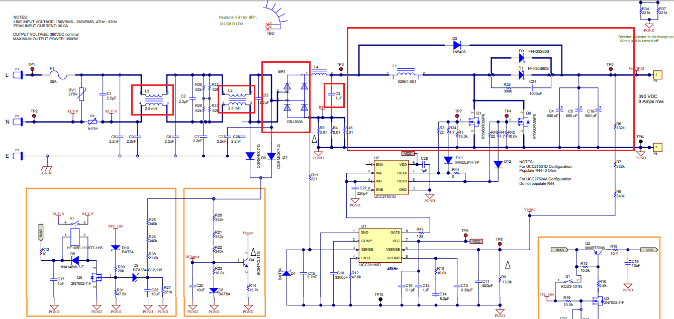
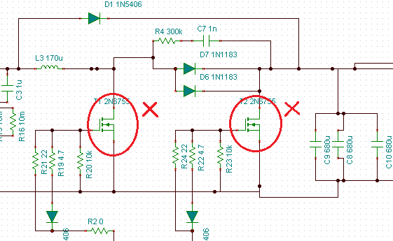
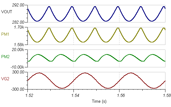
I am currently try to simulate reference 3.5kW PFC design on Tİna-ti. However, ı could not achieve. There is no output signal going to mosfets. if ı trigger with dummy source, there is an square-wave output.

(reference design  http://www.ti.com/lit/df/tidrka5/tidrka5.pdf)  

SimplePFControlleremail.TSC

  • Hi,

    FYI, One of our team member will take a look at this

    Herman
  • Hello,

    I looked into your test schematic. Could you please double check if your design connections and component values are same as per the highlighted (red) sections in reference schematic?

    After modifying if you still face the same issue, please let us know. Also, don't forget to attach the updated test schematic.

    Thanks & Regards,

    Arpan Gupta

  • Hi Arpan,

    Thank you for your quick response.

    -I could not find GBJ3506 spice model.

    -I fixed EMI filter inductors as a 2,5mH

    -L1 value is written as a 780uH in PDF, what is the wright value? 29mH??

    -I could not find FFH30S6 diodes and IPW60 mosfets in spice model

    -I added the 1uF capacitor.

    I still have the problem.5481.SimplePFControlleremail.TSC

  • Hello,

    I just checked the internal model implementation of UCC28180 and observed that transient model is derived from Average/AC model. The GATE pin generates average value of switching waveform. Therefore, we will not observe transient switching waveform at GATE pin. Even we cannot use transient switches/MOSFETs in test schematic.

    In order to make it work we need to use the Boost average switch model instead of MOSFETs (as used in released test schematic).

    The BOOSTCCMDCM includes Average model implementation of Boost switch. Pin D reads the duty cycle i.e the average voltage of switching waveform coming from GATE pin.

    Hence I request you to use BOOSTCCMDCM module instead of MOSFETS in your design. For reference please analyse the TINA-TI transient reference design present in TI website.


    Thanks & Regards,

    Arpan Gupta

  • Hi Arpan,

    Simulation is running but power efficiency is very low. İt may be resulted due to 1N5404 usage. (I could not find FFH30S60S). ı want to integrate my 3.5kW circuit the PFC, however ı could not smulate it :(3683.SimplePFControlleremail.TSC

  • Hello,

    I simulated the test schematic you shared. It simulates fine. Below is the simulation result.

    Could you please explain the issue you are facing in detail?

    Thanks & Regards,

    Arpan Gupta

  • Efficiency is the problem. PM1/PM2<%20 PM1 output power on 50ohm. PM2 is the input power. Acccording to the sample design efficiency must be bigger than %98.
  • Hello,

    I checked the internal implementation of BOOSTCCMDCM block. It includes Average model implementation of Boost switch. This might not replicate the exact input power drawn by actual device. Hence, we will not able to observe proper efficiency value. Sorry for the inconvenience.

    Rather I would suggest you to analyse output voltage, output current using model simulation.

    Thanks & Regards,

    Arpan Gupta

  • Rapan,

    Efficiency simulation is the most important requirement in my design. The PFC module is the last part of the design. Could you offer another .TSC file of bigger or equal 3.5kW, 220 AC input PFC? it may be other topologies, bridgeless PFC, etc.