Tool/software: TINA-TI or Spice Models
I'm trying to model full-bridge power converter in Tina-Ti and need isolation of transistor gates. Found good optocoupler from Vishay 6N137 and Spice model for it. Here is model listing:
**************************************************
* Library of 10MBd HighSpeed Optocoupler 6N137
* Copyright VISHAY, Inc. 2016 All Rights Reserved.
**************************************************
**************************************************
** PSpice Models of Vishay optocouplers
** High speed 10 MBd
** 6N137,VO2601/2611,VO2630/2631,VO4661
**************************************************
**
**************************************************
**  enable- high, NMOS output
**  --  6N137,VO2601/2611 ---
**************************************************
**
** Model Node - Symbol - Pin
** 1 (DA)       A         2
** 2 (DK)       K         3
** 3 (GND)    GND         5
** 4 (VO)      VO         6
** 5 (VE)      VE         7
** 6 (VCC)    VCC         8
**
*$
.SUBCKT 6N137  DA DK GND VO VE VCC
dD1  DA 6  DEMIT
vV1  6  DK  DC 0
wW1  VCC 7  vV1  I_SW1
rR3  GND 7  1K
xU2  7 VE 8 $G_DPWR $G_DGND AND2
rR4  8  9 5K
rR5  VCC VE 100K
MQ1 VO 9 GND GND MOST1 W=9.7M L=2U  ;NMOS OUTPUT
.MODEL    DEMIT   D
+IS=1.69341E-12 RS=2.5 N=2.4  XTI=4
+EG=1.52436 CJO=1.80001E-11 VJ=0.75 M=0.5 FC=0.5
.MODEL MOST1 NMOS (LEVEL=3 KP=25U VTO=2 RD=45 )
.MODEL I_SW1 ISWITCH (Roff=1e6 Ron=1 IT=4.9m IH=0.1m TD=20ns)
.ENDS
*$
**************************************************
**  dual channel, NMOS output
**  --  VO2630/2631, VO4661 ---
**************************************************
**
** Model Node - Symbol - Pin
** 1 (A1)       A1        1
** 2 (K1)       C1        2
** 3 (K2)       C2        3
** 4 (A2)       A2        4
** 5 (GND)      GND       5
** 6 (VO2)      VO2       6
** 7 (VO1)      VO1       7
** 8 (VCC)      VCC       8
**
.SUBCKT VO2630 A1 K1 K2 A2 GND VO2 VO1 VCC
** CHANNEL 1 **
DD1 A1 61         DEMIT
vV1 61 K1  DC 0
wW1  VCC 71  vV1  I_SW1
rR13  71 GND  1K
xU11 71  81 $G_DPWR $G_DGND BUF
rR41  81  91 5K
MQ11 VO1 91 GND GND MOST1 W=9.7M L=2U  ;NMOS OUTPUT
** CHANNEL 2 **
DD2 A2 62         DEMIT
vV2 62 K2  DC 0
wW2  VCC 72  vV2  I_SW1
rR23  72 GND  1K
xU12 72  82 $G_DPWR $G_DGND BUF
rR24  82  92 5K
MQ1 VO2 92 GND GND MOST1 W=9.7M L=2U  ;NMOS OUTPUT
**
.MODEL    DEMIT   D
+IS=1.69341E-12 RS=2.5 N=2.4  XTI=4
+EG=1.52436 CJO=1.80001E-11 VJ=0.75 M=0.5 FC=0.5
.MODEL MOST1 NMOS (LEVEL=3 KP=25U VTO=2 RD=45)
.MODEL I_SW1 ISWITCH (Roff=1e6 Ron=1 IT=4.9m IH=0.1m TD=20ns)
.ENDS
*$
**$
***-------------------------------------------------------------------------
**  1 INPUT BUFFER
**
.SUBCKT BUF  I0  O  optional: DPWR=$G_DPWR DGND=$G_DGND
U1 BUF DPWR  DGND I0  O
+  D_PLD_GATE IO_PLD
.ENDS
*$
***-------------------------------------------------------------------------
**  1 INPUT INVERTER
**
.SUBCKT INV  I0  O  optional: DPWR=$G_DPWR DGND=$G_DGND
*
U1 INV DPWR  DGND I0  O
+  D_PLD_GATE IO_PLD
*
.ENDS
*$
***-------------------------------------------------------------------------
** ENABLE HIGH BUFFER WITH TRI-STATE OUTPUT
**
.SUBCKT BUFTH  I0 OE  O  optional: DPWR=$G_DPWR DGND=$G_DGND
U1 BUF3  DPWR  DGND I0 OE  O
+  D_PLD_TGATE IO_PLD
.ENDS
*$
***-------------------------------------------------------------------------
** ENABLE LOW BUFFER WITH TRI-STATE OUTPUT
**
.SUBCKT BUFTL  I0 OE  O optional: DPWR=$G_DPWR DGND=$G_DGND
U1 INV DPWR DGND OE OEBAR
+  D_PLD_GATE IO_PLD
*
U2 BUF3 DPWR DGND I0 OEBAR  O
+  D_PLD_TGATE IO_PLD
.ENDS
*$
***-------------------------------------------------------------------------
* 2 INPUT AND GATE
*
.SUBCKT AND2 I0 I1 O  optional: DPWR=$G_DPWR DGND=$G_DGND
U1 AND(2) DPWR  DGND I0 I1  O  D_PLD_GATE IO_PLD
.ENDS
*$
*-------------------------------------------------------------------------
.MODEL D_PLD_GATE  UGATE
*$
.MODEL D_PLD_TGATE  UTGATE
*$
.MODEL D_PLD_EFF  UEFF
*$
.MODEL D_PLD_GFF  UGFF
*$
.MODEL IO_PLD  UIO
*$
**==================================================================*
* Note:                                                             *
* Altough models can be a useful tool in evaluating device          *
* performance, they cannot model exact device performance           *
* under all conditions, nor are they intended to replace            *
* breadboarding for final verification!                             *
*                                                                   *
* Models provided by VISHAY Semiconductors GmbH are not             *
* as fully representing all of the specifications and operating     *
* characteristics of the semiconductor product to which the         *
* model relates.                                                    *
* The models describe the characteristics of typical devices.       *
* In all cases, the current data sheet information for a given      *
* device is the final design guideline and the only actual          *
* performance specification.                                        *
* VISHAY Semiconductors does not assume any liability arising       *
* from the model use. VISHAY Semiconductors reserves the right to   *
* change models without prior notice.				        *
**==================================================================*
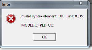
When I create Macro for this opto in Tina-Ti, I get an error
It's clear that problem is in the UIO statment which is Pspice directive. Does Tina-Ti have support of this directive? If not, can I use some other for replacement?


