This thread has been locked.

If you have a related question, please click the "Ask a related question" button in the top right corner. The newly created question will be automatically linked to this question.

TIDA-00792: BQ78350-R1 would not connect to BQstudio

Part Number: TIDA-00792
Other Parts Discussed in Thread: BQSTUDIO, BQ76920, , BQ78350-R1, EV2400, BQ76940

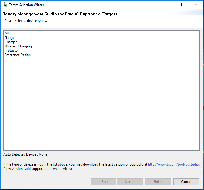
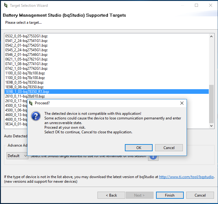
I have made my own board using the reference design (TIDA-00792). I have connected the battery and cells, and on boot up I successfully see BQ76920's REGOUT go to 2.5V and CAP1 go to 3.3V. This REGOUT feeds into the VCC pin of BQ78350-R1. But when I connect the gauge to the BQstudio using the SMBus and EV2400, the gauge would not show as connected. Can you plz guide what's wrong?

p.s. I have attached three pictures that show the BQstudio would not automatically detect neither would it connect once after I manually select the gauge.

Thanks,

Taha

  • Hi Mohammad,

    It looks like something is preventing communication between the EV2400 and the BQ78350-R1 device. Here are a few things to check:
    - I see there are no pull-up resistors for the BQ78350-R1 SDA and SCL lines.
    - Measure the voltage on the REGOUT pin of the BQ76940 (this supplies VCC for the BQ78350-R1). It should be showing 3.3V. If it is not showing a voltage, the device is in SHIP mode and needs a rising voltage on the TS1 pin to come out of wake-up. If you have a button (S1), this can be accomplished by pushing this button.

    Best regards,
    Matt
  • Hi Matt,

    TY for the reply. I have the SDA and SCL lines pulled up to VCC (REGOUT) with 10 kOhm resistors. After booting up (by pressing S1), the voltage on the REGOUT pin of BQ76940 (incorrectly mentioned as BQ76920 in my first thread), which supplies VCC to BQ78350-R1, is 2.5V and not 3.3V. Is that the issue? I thought REGOUT supplies 2.5V. Can I change how much voltage REGOUT can supply? The voltage on the REGSRC pin is 12V.

    Plz let me know if there could be other issues as well.

    Thanks,

    Taha

  • Hi Mohammad,

    I think this is the problem. If you look at Table 4 in the BQ76940 datasheet, there are different part numbers for this device. The different part numbers have different options for the REGOUT voltage (3.3V is needed for the BQ78350-R1), different I2C addresses, and whether CRC is used on the I2C. You will need to change to the correct part number. You may be able to supply 3.3V externally if you are able to disconnect REGOUT - this will allow you to communicate to the BQ78350-R1 while you wait for the correct part number.

    Best regards,
    Matt
  • So, I'm using BQ78350DBTR-R1 and BQ7694000DBT (exact product numbers). I want to believe that the difference in voltage is the only issue, but can you plz confirm now that you have the exact product numbers. Unfortunately the datasheet I have for the BQ78350DBTR-R1 says the absolute maximum VCC it allows is 2.75V (table 2) and the nominal VCC is 2.5V (table 4). I just want to make sure I don't destroy my gauge by providing 3.3V. Additionally, can you plz provide the product number for the AFE that will provide 3.3V on REGOUT pin to correctly power up the BQ78350DBTR-R1.

    Your help is greatly appreciated.
    Thanks,
    Taha
  • I'm sorry, you are correct about the BQ78350-R1 VCC voltage. 2.5V is the correct value, so the device you are using (BQ7694000) should not be an issue.

    I am not sure why the communication with the device would not be working in that case. You should be connecting to the SMBus port (Port 1) on the EV2400 and should be able to observe waveforms on the SCL / SDA pins. When you open BQStudio, maybe you can try to click on the button near the bottom to select the SMBus address or scan for the address - this is just in case BQStudio is not seeing the address it expects.

  • Hi Taha,

    Let me know if you have made any progress with this issue. I will go ahead and close this thread and if you respond with more information it will automatically reopen.

    Thanks,
    Matt