Part Number: TIDA-01455
Tool/software: Code Composer Studio
Hey all,
We are trying to run TIDA-01455 which was produced by given reference design. We have connected it to LAUNCHXL-F28379D by twisted wires (photo below).
It works in common, but at the 200-250 V on the Udc bus, driver LMG3410RWHT starts sending fault signals to the controller.
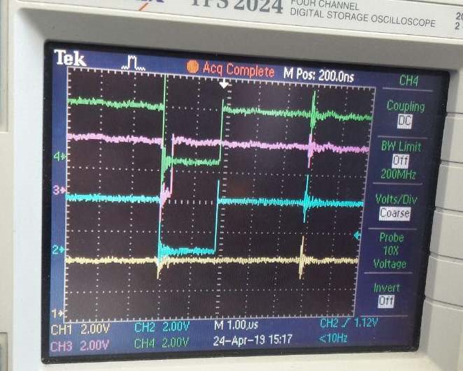
Our first guess was interference and noise to fault wire but the oscilloscope has displayed this:
Cyan - muxed fault signal from all legs;
Green - fault signal phase U
Red - fault signal phase V
Yellow - fault signal phase W
PWM frequency is 100kHz, dead time 200us, current 0.5A, temperature 40-50 degrees Celsius.
According to the LMG3410RWHT datasheet, the fault reset time is 350us. Also, there is description: "LMG3410R070 provides 1) latched OCP option, by which the FET is shut off and held off until the fault is reset by either holding the IN pin low for more than 350 microseconds or removing power from VDD."
So, we have understood it in such a way that fault signal _shorter_ than 350 us is impossible. Is it correct?
But our tests showed that one leg generates 2us fault width, another 0.2us. Why? Also, we have connected the oscilloscope to fault signals of the driver of one leg directly (FLT_T and FLT_B pins at the output of the optocoupler) and have got the same picture - both switches (top and bottom) generate 0.2us faults simultaneously.
It looks like it is not noise or interference on our messy long interconnection wires - fault signal is clean and reproducible.
Why fault happens is an interesting question too, but the first question - is it a real fault? Why is signal so short? How to investigate the reason?
What we did:
1) Checked power supply on drivers during fault - it is ok;
2) Reproduced the problem several times - fault time and leg changes, but approximately it is 0.2-2us on average;
3) Connected more ground wires; twist PWM wires with the ground; twist fault wire with the ground;


