This thread has been locked.

If you have a related question, please click the "Ask a related question" button in the top right corner. The newly created question will be automatically linked to this question.

TINA/Spice/UCC27524: pspice model accuracy regarding output current pulse amplitude

Part Number: UCC27524
Other Parts Discussed in Thread: TINA-TI,

Tool/software: TINA-TI or Spice Models

Hello, 

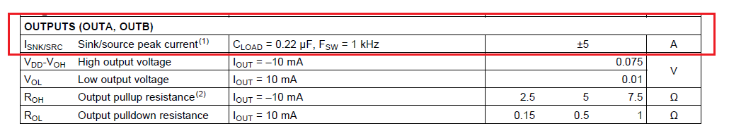
I am using the unencrypted pspice transient model for UCC27524 in LTspice. As an experiment, I connected the driver output directly to a 8100pF capacitor with no external gate resistor in the simulation. Purpose is to verify the dynamic pull high an pull low resistance inside the gate driver. The simulated gate pulse current is less than 4.2A for both pull high and pull low, while the gate driver is powered by 7.5V voltage source. This indicates the internal resistance is around 1.7 ohm which is larger than datasheet value. The power supply is then increased to 15V. This time the gate current peak is clamped flat to 5.30A(source) and 5.65A(sink). Increasing the power supply voltage doesn't change the clamped peak current amplitude. 

Can you clarify if the unencrypted pspice model is accurate regarding the gate current pulse? Is the model reliable to evaluate the dynamic internal resistance of the driver during switching transience? Is the TINA model or encrypted pspice model more accurate? Does the physical device also have output current clamp?

Thank you.

Zhenyu

  • Hi Zhenyu,

    FYI, one of our team will take a look at this.

    Herman
  • Hi Zhenyu,

    TINA-TI model and encrypted PSpice model are using the same .lib file and hence are similar.

    As per datasheet the maximum output Sink/Source peak current is limited to +-5A.

    Also, We need some time to comment on the model reliability on resistance of the MOSFETs.

    We will get back to you as soon as possible.

    Thanks,

    Vivek Agarwal

  • Hi Herman, Vivek,

    Thank you for your help. I will stay tuned. 

    About the source/sink current limit: so the physical device has internal current clamp circuit to limit the current to 5A? In the datasheet, section 7.1 Absolute Maximum Ratings shows the device can not withstand 5A for more than 0.5us. With all the information combined, can I say that the driver has internal source/sink current clamp circuit to limit the current to 5A (even if output is shorted) but the device should not be allowed to work in this clamp state for more than 0.5us? 

    Thanks,

    Zhenyu

  • Hi Zhenyu,

    Vivek is working on it. He will get back to you.

    Thanks,
    Somen
  • Zhenyu,

    Thanks for your interest in our driver.

    My name is Mamadou Diallo, I am the AE supporting low-side drivers.

    The drive current capability is limited by the source/sink current capability of the internal pull-up and pull-down on the output stage. Additionally, the internal impedance Roh and Rol of the same plays a role in limiting the peak current capability of the driver.
    Figure 28 from the datasheet illustrates this. There are no internal clamp circuitry on the output stage limiting the drive current.

    Please let us know if you have further applications related questions or press the green button if this addressed your inquiry.

    Regards,

    -Mamadou