A related question is a question created from another question. When the related question is created, it will be automatically linked to the original question.
If you have a related question, please click the "Ask a related question" button in the top right corner. The newly created question will be automatically linked to this question.
At 5V input the current in the inductor goes up by 50%. It looks like it has margin to increase. I will let the designer comment on the feasibility of this request.
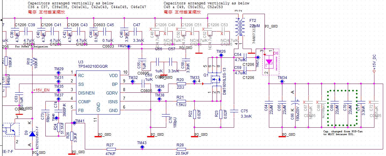
As for the compensation network, TPS40210 is peak current mode control. The output pole is set by the output capacitance and load resistance. The compensation should work as is, but it can be tuned and optimized for 15V/2A.
Hello Terry, PMP30465 has been tweaked to high input voltage 80V by using pre regulator; you ask for 20V input only... Just have a look at my SEPIC PMP30491 using LM25122; this ctrl. is able to handle 3V input and by using synchronous rectification you'll have a nice efficiency, just see my test report. Best regards, Bernd
Hello Terry,
don't know ESR zero of your design, so please do your type 2 loop compensation as follows:
1) calculate right half plane zero RHPZ, it's a function of duty cycle, magnetizing inductance and load resistance;
worst case is at maximum duty cycle - so calculate for lowest input 5V:
RHPZ sepic = (Vout x (1-d)^2) / (2 x PI x d^2 x L x Iout)
2) now set your gain for crossover frequency BELOW 1/5 of RHPZ; if your requirements for dynamic performance are minor
go for Fco of 1/10 of RHPZ, so you will have better gain margin and better phase margin;
this helps if quality of output electrolytic is poor, means ESR increases at low temperatures.
3) now set your compensation zero to twice the load pole
4) now set your compensation pole to 10x Fco; if ESR zero is below 10x Fco set compensation pole to ESR zero;
That's all and you're done, best regards, Bernd