This thread has been locked.

If you have a related question, please click the "Ask a related question" button in the top right corner. The newly created question will be automatically linked to this question.

TINA/Spice: AC load current step change detector

Other Parts Discussed in Thread: TINA-TI

Tool/software: TINA-TI or Spice Models

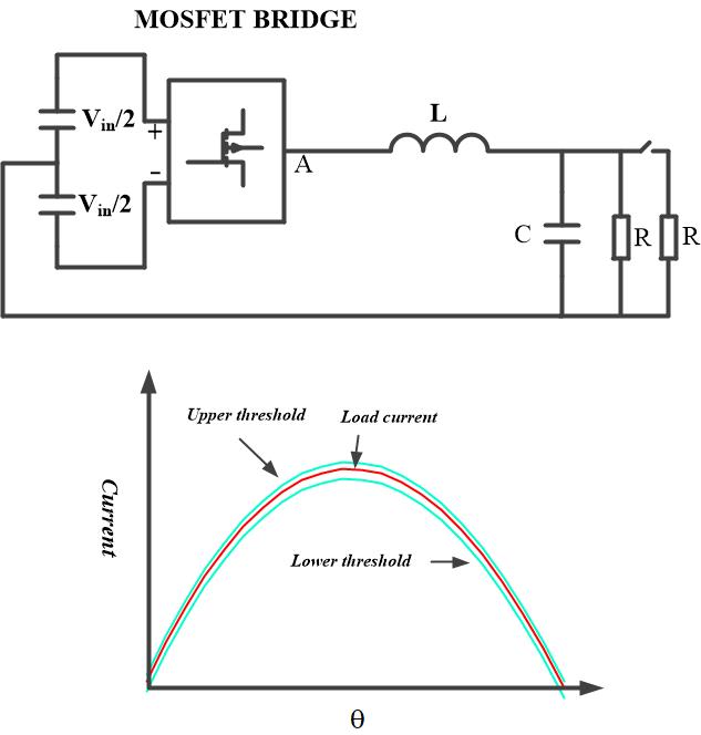
i am thinking how to design  comparator circuit for AC voltage/curtrent  step change. I need to detect AC output voltage/current when there i s load current transient . how to set upper and lower thresholds and if load current/voltage is greater than upper  threshold   send high signal to Microcontroller  or if load current is lower than lower threshold  send high signal to Microcontroller. detection of step change should be so fast that there is  no or very less detection delay.and step change can be at any theta Is it possible to detect step change for non-linear rectifier load 
  • Hi Shah,

    One of our team will take a look at this.

    Herman

  • Hi Shah,

    Do you want to design a comparator circuit using transistor or you want to know how to use comparator in TINA-TI?

    Thanks & Regards,

    Arpan Gupta

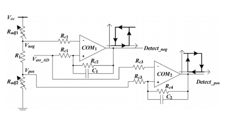
  • i want to design a analog circuit  for both positive and negative step change(ON and OFF) of output load current.  we can pre-define upper and lower thresholds, if step change happens and  greater that upper threshold it means positive step change has occurred and if step change is lower than lower threshold it means negative step change has occurred  for AC linear and non linear load. Below circuit is used for DC- load current step change. i want to design for AC linear and non linear load and how to make AC upper and lower thresholds show in first diagram. thanks

  • Hi Shah,

    I am not 100% sure, but I think what you're trying to accomplish is possible. You just need to choose the right comparator for the speed of detection you need as well as some kind of analog algorithm so that your reference point can always be changed with theta.

    Herman

  • could you please tell me how to implement that analog algorithm that reference point will always change with theta?

  • Hi Shah,

    Unfortunately, we don't have exact implementation that we can offer you. I would recommend to google and search for it. However, from my past experience with working with similar things such as RMS detector etc, what you do is that you translate from the your need/graph into mathematical equations. Then you cut those mathematical equations into pieces or smaller building blocks so that you can translate it into specific circuit implementation.

    Looking at your graph above, it seems your first step will be to translate the Y(x) as a function of x where your Y(x) is your current and then your x is your theta. Then based on the mathematical equation/property, you start translating it into fundamental circuit building blocks.

    Herman