This thread has been locked.

If you have a related question, please click the "Ask a related question" button in the top right corner. The newly created question will be automatically linked to this question.

PMP11254: TPS23751 design POE heatup

Part Number: PMP11254
Other Parts Discussed in Thread: TPS23751, , TPS23753A, TPS2121, TPS2120

Hi,

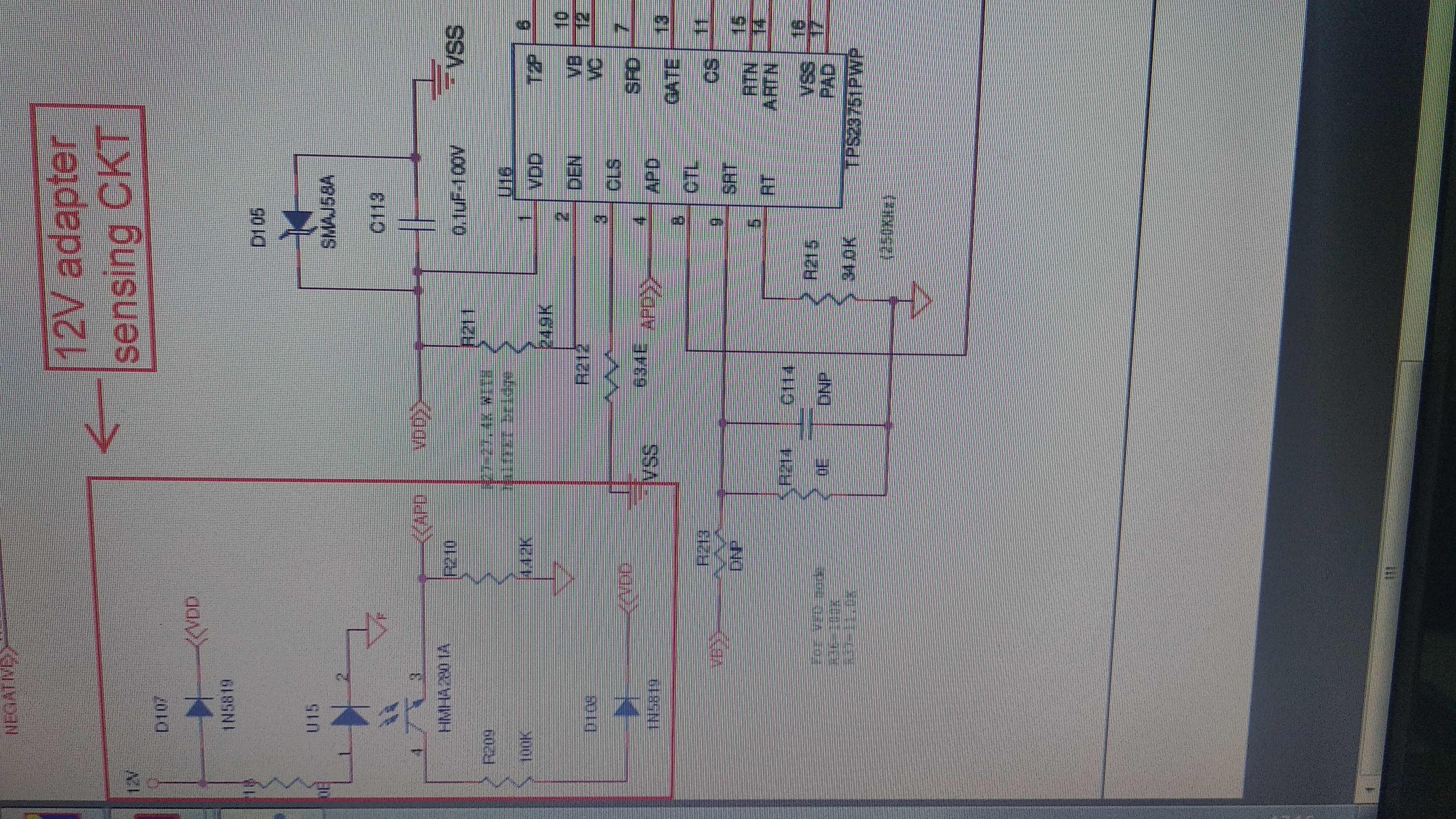
We have design our product using 12V,2.125 A POE .It Working fine but More heat up with 12V, 1amp Load.

It is approx 65-70 degree cen , on Transformer,output diode ,TPS23751,PCB around Transformer, etc

please guide us to reduce heat .

Regrads,

Irfan

  • Irfan,

    The components should not be getting this hot at 1A load.  On the PMP11254 prototype board at 2.125A load the primary FET is 45C, the transformer is 35C and the output diode is 58C.  Did you use the same components/packages as the PMP11254 board?  Is the switching frequency 250kHz?  Do you have airflow for cooling or any other heatsinking?  If not, the only way to reduce the temperature is add more copper to the hot components and make the PCB larger.  Hot components should not be placed directly under each other on the PCB.  The converter is approximately 89% efficient from 1A to 2.125A load.  I don't think much can be done to improve the efficiency.  Is this the efficiency you measure at 1A load?

    David

  • Hi,

    We have used Same components /Packages as per PMP11254.

    Operating freq is 250 Khz .We have used IP65 Enclosure for this product. Our target Load current in max 1A. system working on up to 1A

    We have taken care in pcb layout also.please suggest more to get max efficiency .

    we have notice that POE restart at 1.5A load.

    Regards,

    Irfan 

  • I think the converter is already at max efficiency.  There must be something wrong since it shuts down at 1.5A load.  Can you provide a schematic for me to review?  Can you send me the waveform of the primary FET drain voltage?

    David

  • Hi,

    Please find the attached Schematic of POE 12V, 2.125A .Only Pencil mark components are change as per indicate.

    Also find the waveform of Drain Voltage @ 100mA,700mA,1A and 1.5A .

    we have noted one thing that Web Link switch support 802.3af thats why 1.5A not working

    Please suggest for to get max efficiency and reduce heating.

  • There is no significant ceramic input capacitance.  L11 is acting as a resonant inductance driving the converter.  It appears C102 at one point was a 2.2uF/100V ceramic cap and was changed to a 0.1uF cap.  C102 should be changed back to 2.2uF at a minimum.  I would recommend two 2.2uF ceramic caps.

    Most of the power dissipation occurs in the primary FET, transformer and output rectifier.  These have already been selected to maximize efficiency.

    Without the 2.2uF ceramic input capacitors most of the high frequency input ripple current is passing through L11 and C101.  This results in core/copper loss in L11 and losses due to high ESR in C101.  Once you add the 2.2uF ceramic caps this current will circulate through them and reduce losses in L11 and C101.  Also, the resonance will not be present on the primary FET (and transformer and output rectifier).  This should also reduce losses.

    I can't tell from the schematic, but it looks like the output capacitors are aluminum electrolytic.  There is also high frequency pulsating output current that has to pass through these capacitors.  There should also be some significant ceramic output capacitance to carry this current.  My original design had four 22uF/16V/1210 ceramic capacitors.  Adding these capacitors should reduce the losses by not having the high frequency ripple current passing through the high ESR of the aluminum capacitors.

    Also, without the ceramic input and output capacitors, the ripple current rating of the aluminum capacitors is most likely being exceeded.

    Thanks,

    David

  • Hi,

    We have update as per your suggestion .

    Now we have use Adapter Orig circuit .Using APD function we want to cuttoff POE when 12V (VIN) connect.

    but POE can't cuttoff by using Adapter Oring circuit. we have change ADP divider resistor as per 12V adapter sensing circuit .

    Note-D108 is not connect and sorted that place.

    Please guide us for ADP function to cutoff POE.

    POE_v03.pdf

  • App Note SLVA306A shows various adapter OR-ing solutions for the TPS23753A (these also work on the TPS23751/2/4/6/7).

    It appears you are implementing Option 2 in Figure 1 by inserting the 12V adapter between VDD/RTN for adapter priority.  With this configuration the opto coupler is not required.  You can use a resistor divider from the 12V adapter input to APD, as shown in Figure 8.  A voltage higher than 1.5V on APD turns off the PoE hot swap FET.

    Note:  The PA2467NL xfmr will not work with a 12V input.  The turns ratio is not correct.  It is designed for a 33-57VDC input.

    A better solution may be to OR the 12V adapter directly into the 12V output using Option 3 in Figure 1.  For adapter priority that disables the PoE input you can use the circuit in Figure 10.

  • Hi,

    Our POE circuit will operate on 48VDC input .through D-Link Switch. Actually we have pcb designed as per PMP11254 and send Waveform you also.

    after that we have changed only Transformer PA2467NL due to reduce Height of components. PA2467NL also test with PMP11254 circuit.

    Please let us know that we can use PA2467NL replacement of wurth 7491195112 Transformer or not  for 12V, 2Amp load?


    We have tried with option-3 but POE power Disable when Secondary power is present using DEN.

     Then we have tried with APD pin.We have put opto coupler due to 12V is Adapter power (secondary power) power.

    Now by using APD pin APD voltage change between 0-1.5V ,Gate pulse on/off and POE output is on/off.

    Please note that we want to cutoff POE power when 12V Adapter (secondary power) connect.also POE will work always when connect first or last then Secondary power.

    Please advice to resolve APD Oring or to suggest best.

    Regards,

    Irfan


  • The PA2467NL xfmr should work ok.  The turns ratio for the bias is lower by 10%, but should still be ok.  It operates from a 33-57V input, but not a 12V input.

    Are you trying to do a seamless transition between PoE power and 12V adapter?  If so, the PSE needs to stay connected and the flyback converter needs to keep operating when the adapter is connected.  You also have to maintain the MPS load of 10mA on the PoE input for the PSE to stay connected.

    The TPS2120 and TPS2121 (3A and 4A) is a power multiplexer that can be used for seamless transition.  One channel is the PoE 12V output from the flyback converter and the other is the 12V from the adapter.  You can select which channel has priority if both are connected.  The multiplexer provides seamless transition between the two inputs.

    For the MPS load, you can add a series resistor/zener diode across the VDD/VSS input as shown in Figure 11 of SLVA306A or simply add a resistor on the 12V flyback output sufficient to keep the input current draw at 10mA.