This thread has been locked.

If you have a related question, please click the "Ask a related question" button in the top right corner. The newly created question will be automatically linked to this question.

TIDA-01487: Design works up to 800khz, but behaves oddly at 1 mhz

Part Number: TIDA-01487

I've been working with this reference design myself, at first with my own board, but more recently with the exact board files that TI gives in their reference design page. I've found that I can run the CAN just fine at 800 khz but when I bump up the communication rate to 1 mhz I start to get strange behavior on the bus. The most obvious symptom is the bus usage immediately jumps to near 100%. When probing with a scope, I can see that after a message ACK bit, the bus will return briefly to the recessive state then get pulled low again, remaining locked low until the transceiver times out and resets. 

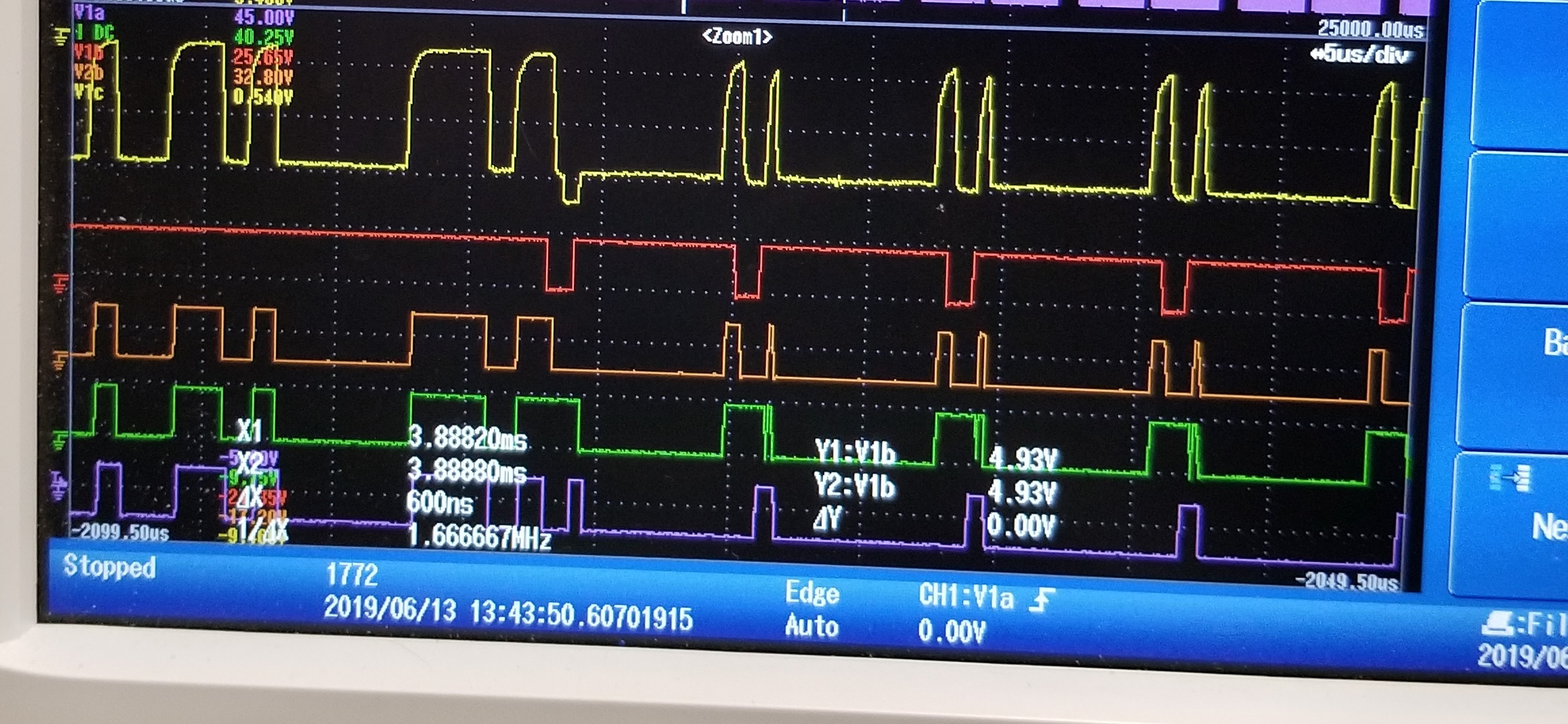
In the above image, the bright yellow trace is the can line logic, red trace is TX1, orange trace is RX1, green trace is TX2, and the purple trace is RX2 . About two-thirds of the way through he shot, You can see a message is ended with an ACK bit (red line going low the first time). This locks the bus in a dominant state until the transceiver times out, only to be pulled low again. Eventually the bus will recover and send the next message, but at the end of that message it will repeat this cycle. I've tried both increasing and decreasing the time delay on the circuit from dominant to recessive, it either makes no change or completely breaks the communication. Does this sound familiar to anyone working on this circuit at TI?

  • Hi Russel,

    I have worked with the board, but at the moment this does not sound familiar. I would need to re-create a similar test setup.

    Can you describe how you done your test, i.e. what kind of CAN devices you have used? How did you measure the bus usage?

    You mentioned that you are using the exact boards files that you used - does this mean you created the PCB and populated the devices from the TI logic family as we provided in the BOM on the reference design?

    Regards,

     Thomas

  • We were using PeakCan viewer on a windows device to send messages through a peak can usb to can adapter to two power inverters, the isolation being between the PeakCan device and the inverters. Without the isolation the bus was fine, as soon as we inserted the isolation we began having issues. The bus usage was being measured using the PeakCan software, and later we probed again using a GEMAC CanBus tester 2 and found the same sort of results shown here.

    And yes, I sent the board files provided in the reference design directly to a fab house and then populated them myself with the BOM provided. I have also re-created the circuit on other boards using the same parts and found that I got the same behavior.

  • Hi Russell,

    Thanks for your description. We will try to replicate the scenario over here, but it will be only during first half of August time frame. Would this work out for you? Let me also try to discuss this topic with you directly.

    Thanks,

     Thomas

  • Thanks Thomas,

    We're in no rush, for the time being we have another solution being implemented. I'm writing more so I can have a solution ready in case we need it in the future.

    You can email me if you would like, you can use the one associated with this account.

  • Thanks Russel.

    If okay with you I will mark this thread as resolved until we where able to replicate the scenario in our lab.

    I will then update this thread with the outcome.

    Thanks and Regards,

     Thomas