Tool/software: WEBENCH® Design Tools
Hello,
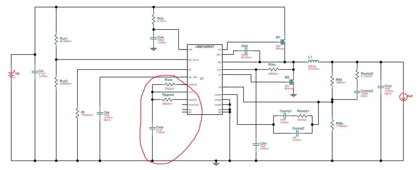
I've been trying out the Webench Power Designer tool, however I'm not sure if a part of the generated schematic is correct.
It shows that the Vcc, PGood and SYNCIN pins should all be connected together and also to a capacitor to ground (circled in red below)
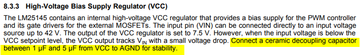
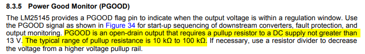
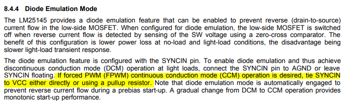
However I believe that only Vcc should be connected to the capacitor, PGOOD should be used as an output (or left disconnected), and SYNCIN depends on whether an external sync input is used or if diode emulation mode is used.
Is there a reason for this design, or is this a fault?
Thanks in advance,
Richard