This thread has been locked.

If you have a related question, please click the "Ask a related question" button in the top right corner. The newly created question will be automatically linked to this question.

TINA/Spice/TIDA-00366: AMC1311

Part Number: TIDA-00366
Other Parts Discussed in Thread: TINA-TI, AMC1311, , OPA320

Tool/software: TINA-TI or Spice Models

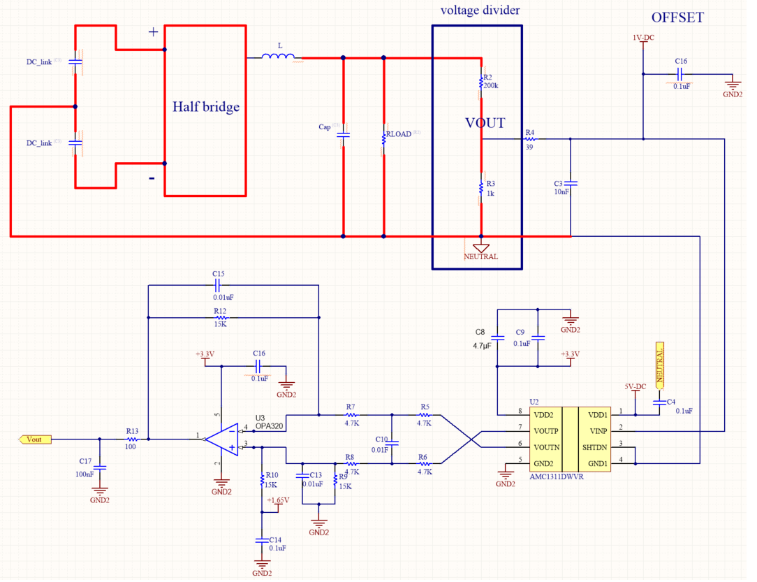
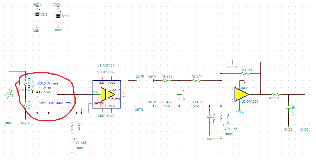
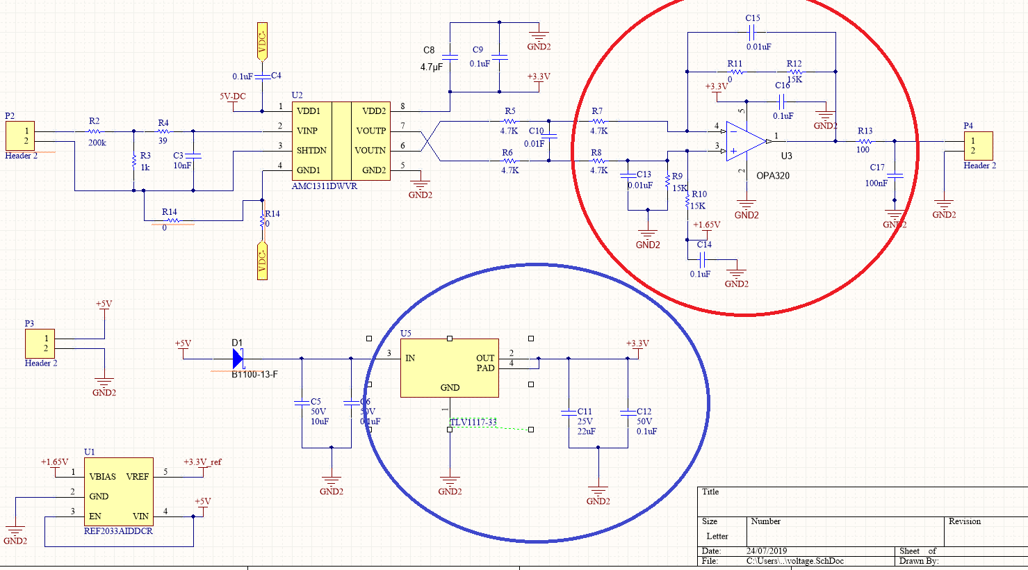
hello,  In TIDA-00366 reference design, for isolated DC-bus voltage sensing AMC1311 is used, my question is that can i use AMC1311 for islolated AC voltage measurement ? 

  • Hi,

    Thanks for the question. AMC1311 can be used to measure AC voltage as long as a suitable positive offset voltage is provided to ensure the VIN voltage is in the (0-2)V range over the entire input signal/waveform.

    TIDA-00366 does not have this positive offset since DC-bus voltage is typically a unidirectional signal.

    Regards

    Siva

  • The  below figure is half bridge DC-AC single phase, its neutral point is connected to mid point of two DC_link capacitors and I want to sense output voltage, voltage divider is used to scale down the output voltage.Point VOUT is connected to VINP and SHTDN andGND1 are connected to NEUTRAL point,  For VDD1 supply  5VDC voltage is generated from 16V using TLV7045 and ground of 16V supply is connected to NUTRAL point. I want to ask this is right or wrong? i have added DC offset voltage in schematic , how can i generate offset voltage ?


  • Hi,

    Thanks for the schematic. I see that the 1V_DC used to provide offset is referenced to GND2 which is the low-side ground. This does not seem correct since offset voltage has to be applied on the high-side and hence should be referenced to GND1 which is NEUTRAL in this case.

    Also, R4 at 39ohms and R3 at 1k means the gain of output voltage is decided by R4 to a large extent and not R3. Please ensure R2, R3 and R4 are correctly designed along with the chosen offset voltage(in the schematic above it is 1V) so that VINP is always within (0-2)V with reference to NEUTRAL(GND1).

    Regards

    Siva

  • i just gave one example of offset voltage, I have generated 1.65 level shift voltage on low side, can i give this offset 1.65 to high side but its ground is GND2 or just connect 1.65 offset and apply groud of high side which is NEUTRAL this case. and I just follow TIDA-00366  and select value of R4=39, and R2 and R3 i just put random values in TINA simulation and saw where scaled down value is within range of AMC1311. My input voltage is 120 VDC and output is 30 AC voltage so i use R2 is 200k and R3 is 1k , could you please recommend me which values I should use for R2, R3 and R4 and which positive offset I will use and how can I generate offset voltage and which differential OPAMP is suitable  thanks

  • Zaman,

    Thank you for your question. 

    We will reccommend you to please take a look at below design resources.

    http://www.ti.com/amplifier-circuit/op-amps/design-development.html

    http://www.ti.com/analog-circuit/circuit-cookbook.html

    Thanks,

    Jasraj

  • In tida-00366 TLV1117-33 is used to generate 3.3 voltage for AMC1311 ,OPA320 and others , I follow Tida-00366 and designed PCB in which I generate 3.3 using TLV1117-33 voltage and gave to MAC1311 and OPA320  but PA320 is not powering on but when I give 3.3 voltage to OPA320 from microcontroller board then it is powering on and I have made PCB hardware. Is there any other way I can turn on OPA320 by TLV1117-33 or do I need to make my hardware PCB again?

  • In tida-00366 TLV1117-33 is used to generate 3.3 voltage for AMC1311 ,OPA320 and others , I follow Tida-00366 and designed PCB in which I generate 3.3 using TLV1117-33 voltage and gave to MAC1311 and OPA320  but PA320 is not powering on but when I give 3.3 voltage to OPA320 from microcontroller board then it is powering on and I have made PCB hardware. Is there any other way I can turn on OPA320 by TLV1117-33 or do I need to make my hardware PCB again?

  • Zaman,

    From what I read above, It sounds like some problem on your PCB itself, since schematic is showing correct net connection. Please check your PCB for these signals.

    Please note, Since it is difficult to test for us, We will not be able to debug your hardware over an E2E thread.

    Thanks,

    Jasraj