This thread has been locked.

If you have a related question, please click the "Ask a related question" button in the top right corner. The newly created question will be automatically linked to this question.

WEBENCH® Tools/TIDA-01573: TIDA-01573, OPA857EVM-978, ADC12J1600EVM

Part Number: TIDA-01573
Other Parts Discussed in Thread: OPA857, OPA857EVM-978, ADC12J1600, LMG1020, LMG1020EVM-006

Tool/software: WEBENCH® Design Tools

Hello,

I'm, working on some device in automotive and I would like to use your products (TIDA-01573 - Nanosecond Laser Driver Reference Design for LiDAR, OPA857EVM-978 - OPA857 Bandwidth Extension Evaluation Module and ADC12J1600EVM - ADC12J1600 12-Bit, 1.6-GSPS, RF Sampling Analog-to-Digital Converter Evaluation Module) into it. I'm preparing this device in 3D software, so I need the 3D data of your products to my work, but I can't find any 3D data on sides of your company. If you have any 3D data, can you send me it please?

Best regards,
Jakub Nigut

  • Hi Jakub,

    Thanks for reaching out and welcome to e2e!

    TIDA-01573 is the same as the LMG1020 EVM and used to showcase LMG1020 driving a laser of your choice for LiDAR applications.

    The bxl CAD files for the components can be found in the TIDA product folder below.

    Check out LMG1020 EVM Users Guide

    As well as the TIDA guide 

    Let me know if you have any questions about these files or through out evaluating and testing the EVM/TIDA.

    Thanks,

  • Hi Jeff,

    thank you for your response. I have a few more questions.
    Have LMG1020 the same dimensions as TIDA-01573?
    LMG1020 is only on "bxl" format and this format can be opened only in "Ultra Librarian Reader" software . In our company is prohibited to install unverified software. For installing of unverified softwares we have a very long approval process, and I can't wait so long. Could you send me 3D data in STEP format?

    Best regards,
    Jakub

  • Hi Jakub,

    Thanks for letting me know. Let me request the step model to be created. Ill let you know when its done later this week or next week and attach a link for download. Let me know if you have any other questions.

    thanks,

  • Hi Jeff,

    Is the STEP file of TIDA-01573 already available? If so, can you send me it please?

    Thank you,
    Jakub

  • Hi Jakub,

    The STEP file for LMG1020 should be available by the end of the week however its possible the modeling team is very busy and might take longer. I will let you know of any updates and post the link when its ready to download.

    Thanks,

  • Hi Jakub,

    Just wanted to let you know the step model is going to take a bit longer than estimated. Let me update you next week with a better eta.

    Thanks,

  • Hi Jeff,

    I will count with it and thank you for information. 

    Best regards,

    Jakub

  • Hi Jakub,

    I just wanted to update you and let you know the lmg1020 step file is ready. There appears to be an issue with automation of step files on the product folder for WCSP packages. I will email it to you offline, please accept my friend request.

    Thanks,

  • Hi Jeff,

    thank you for information, but I suppose that here is some kind of misunderstanding happened. I don't want to the step file of LMG1020, but I need the step file of TIDA-01573. Could you send me this step file please?

    Best regards,
    Jakub

  • Hi Jakub,

    Thanks for the update,

    TIDA-01573 is the same as LMG1020EVM-006. The 3D step file for this EVM as a whole can be created using the altium files. The step file generated is attached as well as the pdf version.

    https://e2e.ti.com/cfs-file/__key/communityserver-discussions-components-files/234/LMG1020EVM_2D00_006.step

    3D model.pdf

    Also the step files for the individual components can be found in the CAD section in the link below, let me know if you have any questions using these.

    Please let me know if this helps answer your question? Feel free to reach back out to e2e for a layout or schematic review.

    Thanks,

  • Hello Jeff,

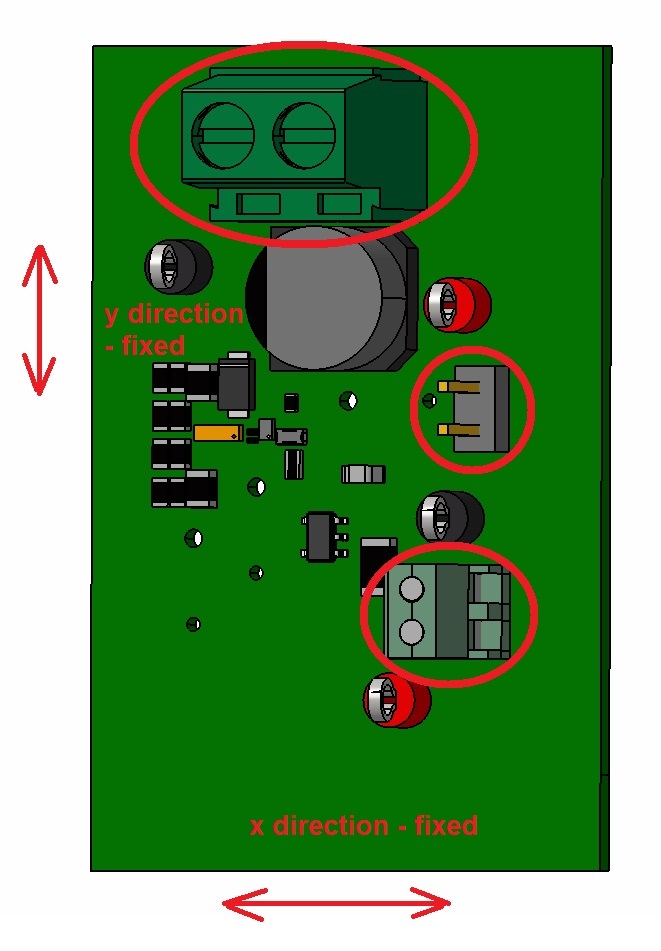
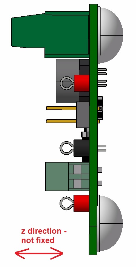
    Thank you for the data. I would like to ask you few more questions about mounting of this PCB. I suppose that PCB should be fully mounted without any degrees of freedom. Next I suppose that these 3 red marked connectors serve to the mounting of PCB, but they removing only 2 degrees of freedom.


    Can you tell me how can I fully fix the PCB? Do you have some holder for it, or some screws?

    Best regards,
    Jakub

  • Hi Jakub,

    Thanks for the follow up question,

    Were you planning on removing the 3 circled components? or using the screw connector terminal to secure it in place?

    It might be possible to remove the bumpons and drill a hole through the corners of the board to mount it to something with screws.

    Thanks,

  • Hi Jeff,

    Thank you for answer and for suggested solution. I will thinking about it.

    Best regards,

    Jakub