A related question is a question created from another question. When the related question is created, it will be automatically linked to the original question.
If you have a related question, please click the "Ask a related question" button in the top right corner. The newly created question will be automatically linked to this question.
Are you trying to integrate laser pulses or to sample and hold? Try using the 20MHz filter in the scope and see if that helps. If so, you can include one in your circuit. You can gain up the signal using another amplifier stage. Another idea is to use a fast, high current output op amp amplifier like the THS3491 to implement a peak detector.
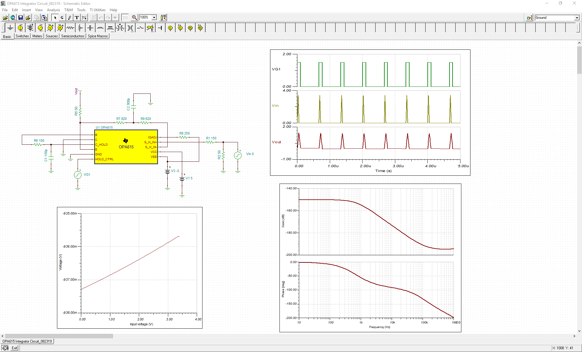
I want to implement a peak detector circuit (or integrator) that holds the sampled value for some specified hold time. The input pulses are ~50ns wide and ~1.5 MHz frequency. They will be sampled by an ADC. I am trying to hold the signal longer for the ADC, that's why the integrator or peak detector-hold circuit. Attached is my simulation of the circuit that I implemented. The actual output of the signal was very low and noisy as I had mentioned before. A couple of questions:
1) Can this circuit be fixed using the high current opamp that you mentioned? Should I use a filtering stage instead?
There are many different ways to build a peak detector. This is an older part, and I was just recommending a faster one. To fix this circuit, you should use a capacitor and diode to do the sample and holding.OPA615PeakDetector.TSC
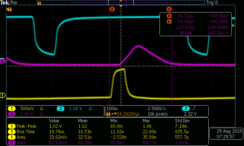
1) My integrator circuit is connected to a high input impedance (>1G ohm) ADC from NI DAQ. I tried to match the impedance with 50 ohm termination resistance but that doesn't seem to get the job done. To simulate this reflection effect I hooked it up to oscilloscope with 1M ohm impedance setting and I still see reflections at the output :
With 50 ohm impedance setting at the oscilloscope, I don't see the reflections anymore:
How do I fix this problem? Do you think a buffer would fix this problem?
2) I tried simulating the peak detector circuit for the input pulses specific to our application and it doesn't seem to hold the peak value. Also, if the peak value of the incoming pulses changes, i.e. say its an incoming pulse stream with voltages varying from 3.4-0.5 V, how do I simulate that?
A 50 termination is good, but did you also add a 50 ohm source impedance at the Vout of the OPA615?
Holding an exact peak value is not really what it is designed to do. It is more of a flip flop that indicates when a peak of any size has been detected. Your pulses are so close together that it is integrating them together and is just winding up. You can decrease capacitor size to have it decay faster, but how often long do you want to hold the peak?
To build a stream with different values in TINA, you will probably need to just build a piece-wise linear coordinate map. You can set it to repeat forever.