Hi,
The other day I taught you to use a voltage control switch as a model for the sample hold circuit at TINA-TI.
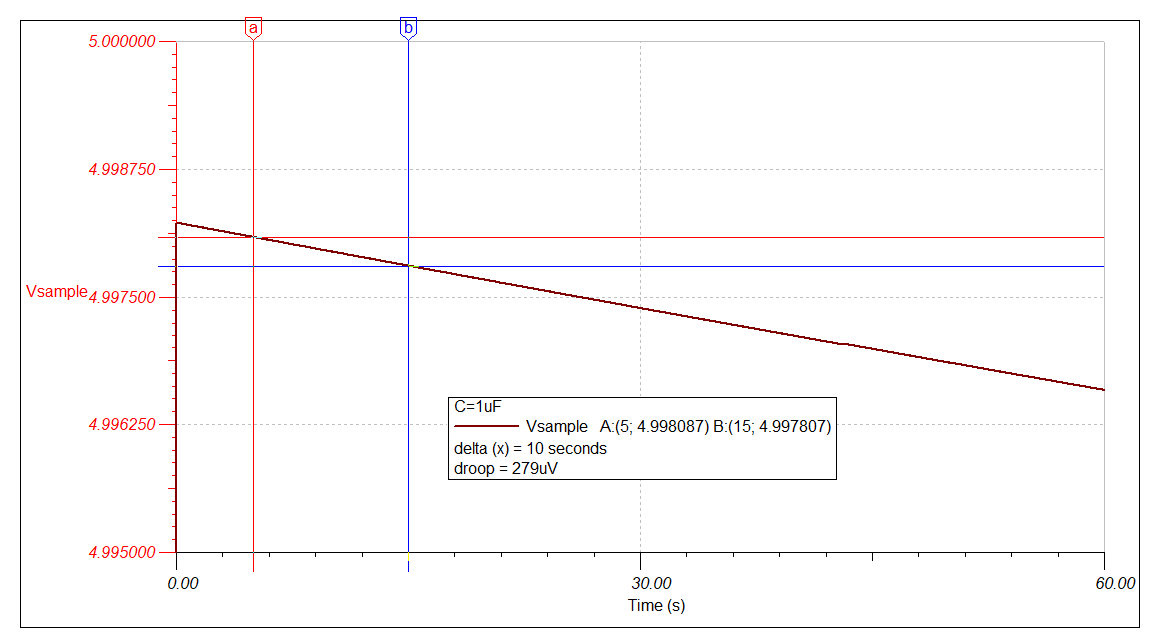
In this case, what should we do to achieve the droop rate of the sample and hold circuit?
Best regards,
Original question:

How to simulate a sample and hold circuit with the TINA-TI tool
Hi,
The other day I taught you to use a voltage control switch as a model for the sample hold circuit at TINA-TI.
In this case, what should we do to achieve the droop rate of the sample and hold circuit?
Best regards,