Part Number: LM3481-Q1
Other Parts Discussed in Thread: LM3481
Tool/software: WEBENCH® Design Tools
Hi
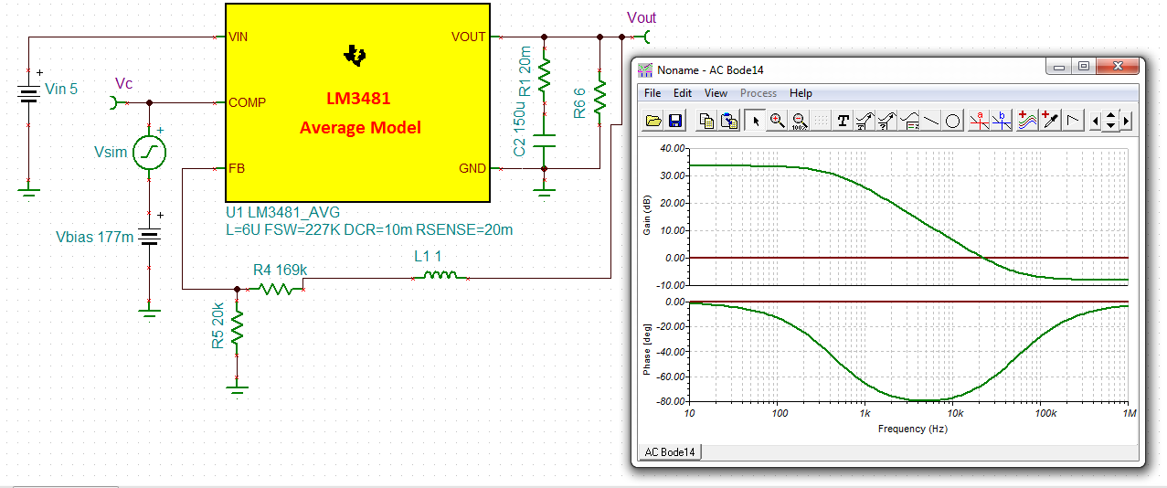
I'm in a real trouble, a trouble that I did not understand its source. First I have downloaded LM3481 average model from TINA TI website, the date of release of this average model is 21/04/2015.
I have built a circuit in TINA TI v9.2, in order to perform an AC Simulation. My objective is to get the open loop of my circuit (the powere stage) that will allow me to place the poles and zeros at the appropriate locations to stabilise my boost converter.
the specifications of the boost converter are:
Vout=12V
Iout=1.8A
L=6u
Fsw=227kHz
Rsense=20m
When i simulate I get a very strange phase diagram, a diagram that has nothing to do with powerstage of boost converter in current mode configuration.
Please, I really need your help, because I have 3 days trying to get the result but I did not.
The circuit I have used is shown bellow and the simulation file is attached.
In the circuit I have set Vc as output and Vout as output.