This thread has been locked.

If you have a related question, please click the "Ask a related question" button in the top right corner. The newly created question will be automatically linked to this question.

beginner with TINA-TI, Irregular circuit

Other Parts Discussed in Thread: TINA-TI


Dear All,

I am new to TINA-TI and i am starting with the "Getting started with TINA-TI"

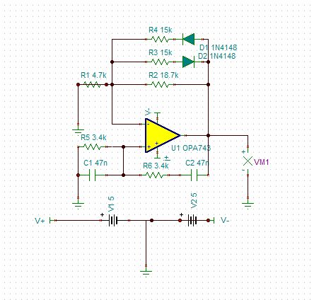
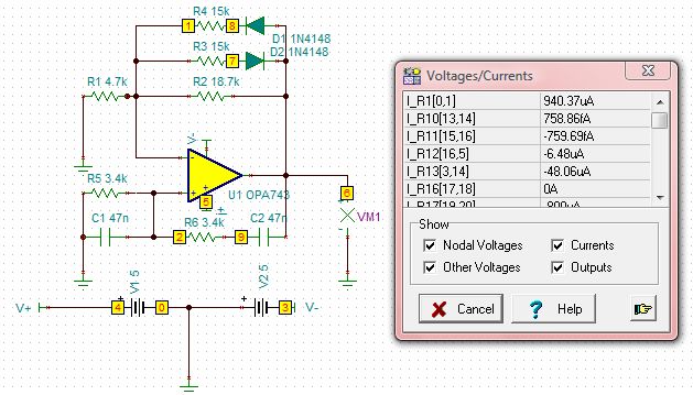
On trying to implement the circuit , the ERC report is all ok but the dc analysis and AC analyses are prompting the message of error "irregular circuit". I am not quite sure about the jumpers, changing their name with the name of the voltage source and the name of the op-amp (V+ & V-) is sufficient to ensure their work??

Please help me with this issue as i am planning to work further in this application.

Best Regards


  • Hi Mahir,


    Comparing the circuit you have shown to the circuit in "Getting started with TINA-TI.pdf", I see that jumper V- is has been shorted to ground and so has the negative terminal of the OPAMP (you can see the wire connection over V2 and R1). You are getting the irregular circuit error since you are shorting the GND net to a net called V-. If you remove the short you will see that the error will go away. Also, for the circuit to work properly, please remove the short across R1 as well.

    Let me know if you have any further issues.

    Best regards,

    Nikhil Gupta

  • Dear Mr. Nikhil,

    Thank you for your great explanation, but i think i didn't get it about the jumper and ground, i am not good in TINA-TI !!!

    Please, provide me with more information, i have made some changes but still irregular circuit.

    Also, how to show the pin numbers od the Op-Amp an TINA-TI triangular model?


    Best Regards


    Mahir

  • Hi Mahir,


    It looks like you were able to remove the wire across R1 based on the schematic that you have attached. If you look closely, you will see that there is another wire over the voltage source V2 (which is shown by the 2 small dots, one just below the + sign and the other on the jumper V-). You will need to remove this wire from the schematic as well(it might have been drawn by accident when you were wiring up the schematic). In addition, you will have to put back the ground between V1 abd V2 as you had previously shown. Please let me know if this solves your problems.


    Best regards,

    Nikhil

  • Dear Mr. Nikhil,

    I think everything is going good, the circuit works properly but still i don't know how to show the pin numbers of the op-amp, i will try another circuits from the "Tina Ver.9 User manual quick start" in order to get more familiar with this great program.

    Please Sir, if you have any suggestions, please write them for me....

    Thank you very much and hoping more and more progress.

    Best Regards

    Mahir

  • Hi Mahir,


    The model that you are using right now is an inbuilt model and the symbol for this model can not be modified to show the pin numbers.


    Nikhil