This thread has been locked.

If you have a related question, please click the "Ask a related question" button in the top right corner. The newly created question will be automatically linked to this question.

Stuck with T&M in TINA-TI

Other Parts Discussed in Thread: TINA-TI, INA2331, TS3A24159, INA331

Dear All, 

thank you very much for helping me and giving me real support  with TINA-TI...

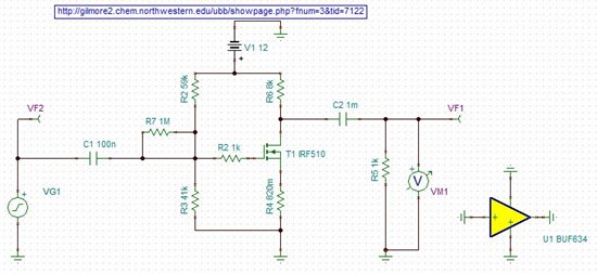
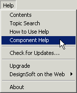
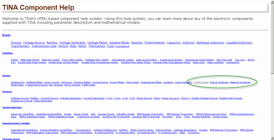
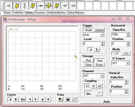
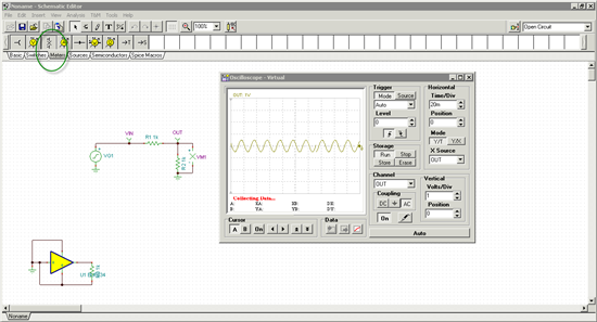
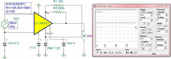
Now, i am planning to run Oscilloscope, signal analyzer, etc. with the attached circuit, but nothing is working with me.

The version I use on TINA-TI is Version 7.0.80.96 SF-TI, Build date: 2009 April 6, 11:48:24 AM and i am not sure how to start the above mentioned measuring techniques.

The circuit is taken form a website: http://gilmore2.chem.northwestern.edu/ubb/showpage.php?fnum=3&tid=7122 


Please Help me, Waiting for your response asap.

Great Respect.

Mahir

  • Hi Mahir,


    You can find help for these components in the TINA Help Menu. Click on Help --> Component Help as shown below.

    This will bring up the Component Help Window as shown below:


    Help on Oscilloscope, Signal Analyzer can be found under "Meters".

    Let me know if you have any other questions.

    Best regards,

    Nikhil Gupta


  • Dear Sir,

    Thank you very much for your concern.

    I reached the Help page, but I don't have the same meter par on my prog. I attached an image of  the meter par and the oscilloscope i see which i get it from the T&M menu.

    It is related to the same circuit so when i open it, no signal appears...

    Thanks in Advance...

    Mahir


  • In your schematic, you will need to place the following meter marked by the green circle below. After you do that, place an oscilloscope from the T&M Window, and click on the run button to observe the waveform.


    I hope that answers your question.


    Best regards,

    Nikhil Gupta

  • Dear Mr. Nikhil,

    Thank you very much for your great support.... Everything works good right  now!!!

    Finally i can use the Oscilloscope, but what about the bode Plot for the circuit?? 

    and is this version of TINA-TI have interactive mode???

    I will try working on IN-AMP in future for more advances in work...


    Thanks again

    Mahir

  • Mahir,


    The  best way to run the Bode Plot is as follows:

    1. Add a Voltage Generator  as follows, and set it to a Sine Wave.


    2. From the Analysis Menu, select AC Analysis --> AC Transfer Characteristics


    3. Set the parameters based on how you want to run the Bode Plot.

    4. Click OK and you should see the results


    Details about how to use TINA, place components, use components and run the different analysis are given in the help menu (either through Contents, Topic Search or Component Help). Please search the menu first and if you still have questions, feel free to post it on the forum.


    Regards,

    Nikhil Gupta

  • Dear Mr. Nikhil,

    Everything is working great right now,  i managed to run the tools in the T&M menu.

    Please, can you help me in selecting switches (hardware, shown in number 1&2) along with timer IC (binary counter) produced by TI. These are to be used with the following parameters:

    1. incoming analog signal: 50uV.

    2. incoming signal frequency: 1 to 12 Hz.

    3. measuring time: Phase 1= 2 Sec, Phase 2= 20 mSec.

    The switched signal will be amplified using INA2331 from TI.

    Best Regards

    Mahir.

  • Mahir,

    I may be able to help, but I need to know more about what you are trying to do - can you post some more information about your circuit or application?

    You ask for hardware switches, do you mean some type of analog switch IC, or actual hardware switches (like toggle switches or something)?

    Also, not sure what kind of timer or counter IC you may need - what are you counting? What clocks it?

    Some more details would help us help you better.

    Rick

  • Dear Mr. Rick,

    Thank you very much for your concern...

    I am planning to amplify a signal of about 50uV and 4Hz, so i need switches to work with such a signal. I think the switch should have a low Ron. The Switches are to be controlled by an IC so that they will work for  one side for about 2Sec. and for the other side for about 20mSec. These switches will be used with INA2331 IN-AMP.

    So please, provide me with the proper IC's I need for the switches and for the controller.


    Regrads.

    Mahir

  • You might consider something like the TS3A24159.

    However, you seem to suggest that you'll be doing the switching on the input signal, before amplification. Analog switches aren't well-characterized for noise, but rest assured they have some - if you're switching a 50uV signal, I can't say how well that might work, even with this very excellent switch. Again, knowing more about your application may help me to make a better suggestion.

    As for what controls the switches, it could be as simple as a 555 timer or as sophisticated as an MSP430 microcontroller. That's up to you, and again, knowing more would help me make a better suggestion.

  • Dear Mr. Rick,

    I was thinking about amplifying the signal before switching, so i tried to build a circuit using the amplifier INA331, and i read the data sheet, the circuit is attached and i don't know what is wrong with it!!!

    So i planned to amplify the signal by 100, and according to the datasheet, i chose R1=10KOhm and R2=190KOhm, and connected the resistors R1 between Rg and Ref and R2 between Rg and Vout, I am not sure if these connection are working good as the oscilloscope signal in flat???

    Also, How can I use Ref pin to remove the IN-AMP offset??

    Be sure that i have the honor to deal with such great engineers and great Company.

    Best Regrads.


    Mahir


  • Mahir,

    It may look like a flat line, but it isn't. I built the same circuit in TINA-TI and it works correctly. 

    With a 50uV signal (that's 100uV p-p), and a gain of 100, your output signal is only 10mV p-p. If you set the oscilloscope up so that its vertical resolution is 10mV/div, and set the Position to -1.25V, you'll see your signal - it is a 10mV sine wave riding on top of 1.25VDC (the reference voltage). You could also just AC couple it to see the waveform quickly if you don't want to mess with the Position...

    As described in the datasheet, the voltage on the REF pin sets the level the output is referred to (like in your case, the signal begins at 1.25V). You could adjust the REF voltage to compensate for any offset in the input stage.

  • Dear Mr. Rick,

    Thank you very much for your health, The circuit really works!!!!

    About the Offset, I checked the datasheet of the In-Amp INA331 and it was 250uV, i am not sure if i can apply this very small voltage practically? Also, can we consider the Ref pin as a null pin of the amplifier??

    Regarding the data sheet, I couldn't find the En pin on the INA2331, is it negelcted or what? and why we apply 4 Volts to it in simulation??

    Thank you in advance...

    Regards


    Mahir

  • Mahir,

    Yes, the offset voltage is very small on the INAx331, you can probably ignore it. The REF pin can be considered a null pin, but it is really used for setting the output reference voltage - if you want to compensate for the input offset using it, you can.

    The INA2331 has shutdown pins on pins 8 and 14. I have no idea why you used 4V in your simulation, but anything over 0.8V should enable the device.

  • Thank you very much Mr. Rick,

    You helped me so much, i am working good with TINA-TI, it is a great application and i am planning to by some IC's from TI to start working practically in some basic circuits, so i am looking for the TI branch in middle east or China.

    Thanks again, and please accept my great respect to you and all TI people.

    Mahir

  • You're quite welcome.

    Follow the "Contact Us" link at the top of this page, from there you can find authorized distributors and sales reps for TI products anywhere in the world.

    Good luck with your projects!