


Part Number: TPS40090
Other Parts Discussed in Thread: LM324
Tool/software: WEBENCH® Design Tools
Hello,
1. I'm configuring TPS40090 steady state reference design from 4 phase into 2 phase design. On top of this, i have already modify the design by using
external compensation circuit and external gate and mosfet circuit. This design has been set to 30V voltage output and 80A current output.
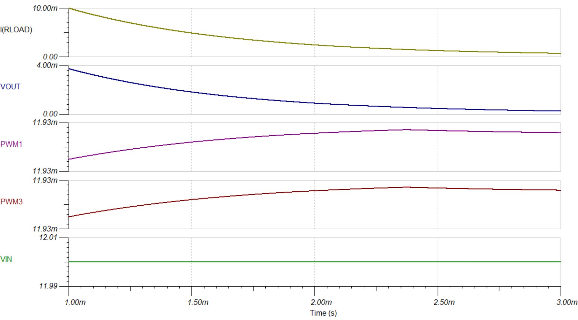
2. I have disabled PWM2 and PWM4 by connecting it to BP5 pin to convert it into two phase design as suggested by the design guide. CS2 and CS4 pin is also connected to CSCN. With this changes. I'm not able to get the desired output with the PWM1 and PWM3 going to max 12V as shown below.
3. But when i connect BP5 pin to a 5V voltage source. I'm able to get the programmed 30V80A output as shown below. May i know is it necessary to connect BP5 pin to a 5V source? Thanks in advance for your support. Attached are the simulation file for both working and not working setup.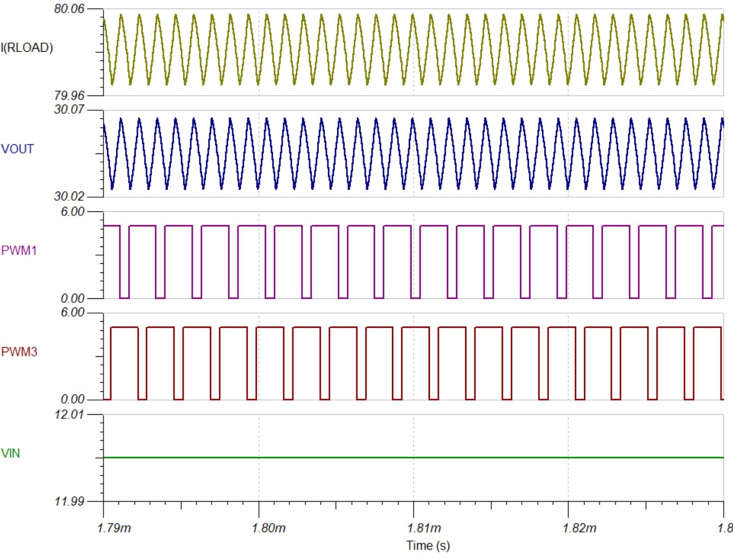
TPS40090_extfeedbck_30V80A_extgdrivefet_working_two phase_working.TSC
TPS40090_extfeedbck_30V80A_extgdrivefet_working_two phase _not working.TSC
