This thread has been locked.

If you have a related question, please click the "Ask a related question" button in the top right corner. The newly created question will be automatically linked to this question.

WEBENCH® Tools/TPS61022: TPS61022

Part Number: TPS61022
Other Parts Discussed in Thread: TPS61023

Tool/software: WEBENCH® Design Tools

Hello everybody.

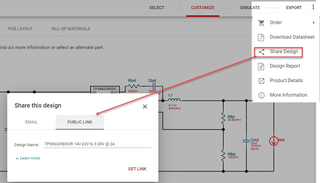
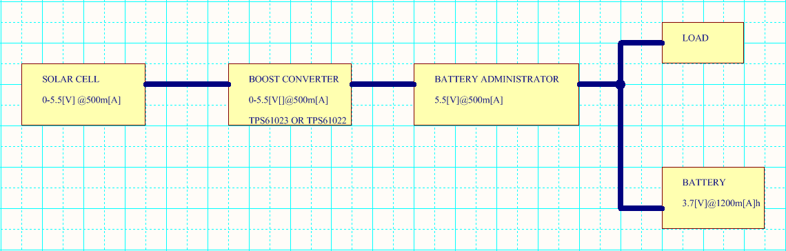
I´m new in this forum, i have been simulating in WEBENCH the boost converter  TPS61022RWUR , I see the configuration and i have to changed some components; the Voltage output is correct; I would like to know if this device can drive up  1000m[A]?

So in the simulation is around 100m[A] current output but I need up 500m[A].

Can I to connect in  cascade with another devices like MCP73871?

Is the same thing with TPS61023DRLR?

THANKS A LOT.

  • Graciano,

    Thanks for your question. Would it be possible to share the input conditions (VinMin, VinMax, Vout, Iout, Ta) you are running the TPS61022 at? Ideally, if you can share the WEBENCH design, that would be good - please see screenshot below for reference. TPS61022 is rated for 8A valley current limit so depending on your input conditions, we may need to check if we hit that limit or not.

    TPS61023 has lower valley current limit of 3.7A. On the MCP73871 cascading question, I am requesting a product expert to comment on it.

    Regards,

    Amod

  • Thanks Amod for answering some questions.

    Hi Graciano,

    Like Amod said, you need to provide the information of Vin range, Vout, Iout, Ta information so that I evaluate if TPS61022 could work in this condition.

    MCP73871 is s Microchip device so WEBENCH doesn't support its simulation. You can find TPS61022 PSpice Transient Model in the link: http://www.ti.com/product/TPS61022/toolssoftware. Download it and simulate the cascaded circuits.

  • Hi Zack Liu.

    I have three questions:

    I have to use TPS61023 but this cannot simulated in WEBENCH, I have been simulated TPS61022; I dowloaded the pspice to simulated but It can simulated in LTSPICE XVII?

    The models in WEBENCH are in ideal model?

    What happen if I use capacitors less value ESR than the simulations?

  • Graciano,

    TPS61023 is enabled in WEBENCH but the electrical simulations are not available for this device in the tool. As you mentioned, you can continue using PSPICE to do your electrical sims. I will let Zack answer on the availability of LTSPICE model for TPS61023.

    WEBENCH models are not based on ideal components. Parasitics in components like MOSFETs, inductors, capacitors, etc. are accounted for while estimating performance variables like efficiency, stability loop response, etc. For caps, we account for ESR and Cap value.You can change the capacitor from the BOM by choosing an alternate component or creating a new custom cap with cap value and ESR value and check the design operating values from the "Operating Values" tab. You can also observe changes in transient performances with changing ESR using PSPICE.

    Regards,

    Amod

  • Thank you Amod Vaze.

    I would like to know if TPS1022 and TPSS1023 do they have the same functioning??

    The simulations between TPS1022 and TPSS1023 could be the same simulations with the same components under the same circumstances?

    Thamk you a lot Amod Vaze

  • Hi Graciano,

    TPS61023 has minimum 2.7A switch current limit while TPS61022 has minimum 6.5A switch current limit over full temperature range. It depends on the input of your working conditions: Vin range, Vout, Ioutmax that if the WEBENCH could work or not. Please share these information with us.

  • Hi Zack Liu.

    I have an solar cell around 5 [V] @ 100m[A], these values are variable, I try to stabilze them.


    I have simulated TPS61022  and I have shared it.

    If I put an other solar cell, the performance will be the same or better?

    I will put an solar cell around Vin=6[V] @350[A] or solar cell Vin=8[V] @450m[A].

    I want to build a circuit with TPS61023 and put an potenciometer in R1 @1M[OHM].

    Why TPS61022 has the pin MODE and TPS61023 it isn´t?

    The working of TPS61023 could work well with the simulation of tps6122?

  • Hi Graciano,

    I'm sorry I didn't find you shared WEBENCH file in this thread. Can you share it again?

    TPS61022 and TPS61023 maximum input voltage is 5.5V so it cannot connect to a 6V or 8V solar cell. Can you share the schematic or system block diagram so that I can get your meaning easily?

    TPS61022 is a 2*2 mm VQFN package device while TPS61023 is a 1.2*1.6mm SOT563 package device. Because of size and pins number limit, we remove the MODE pin in TPS61023.

  • Dear Zack Liu.

    I hope you have a nice day.

    This is the block diagram about I want to do.

    The solar cell can be 8[V]@450m[A], I can control the input voltage maximum; I want to know if the boost converter is ritgh to this configuration and if this can manager the input current.

    The input voltage is variable but i would like to control it with the boost converter then I want to know wich one can I use it, wich is the better choice.

    thanks a lot.

  • https://webench.ti.com/appinfo/webench/scripts/SDP.cgi?ID=A07F2D9EFFF33BA1

    I´m watching the simulation and I would like to know if is necesario a filter in output voltage before of the battery administrator?

    Is the same function between TPS61022 and TPS61023  with the parameters on simulation?

    I've tried to simulate them in pspice cadence but I can´t do it!

    Thanks a lot.
  • the URL for simulations is:

    " https://webench.ti.com/appinfo/webench/scripts/SDP.cgi?ID=A07F2D9EFFF33BA1

    "

  • Hi Graciano,

    Since the input is a 5.5V or 8V solar cell which is higher than the battery voltage range, and you have to implement the Maximum Power Point Tracking (MPPT) control, I think a buck topology solar cell charger IC is more suitable. I draw a simple block diagram shown as below. The charger IC will charge the battery. Another boost converter is needed to boost the battery's voltage to the load needed voltage level. Let me know if you any questions.